


BT RR-30B Reach Truck Repair And Parts Manual 301077-000
$30.00
- Type Of Manual: Repair And Parts Manual
- Manual ID: 301077-000
- : Parts Manual PDF
- Number of Pages: 376
- Size: 17.6MB
- Format: PDF
Category: BT Parts Manual PDF
-
Model List:
- RR-30B Reach Truck
- 1. Front Cover
- 2. Introduction
- 3. Important Notice
- 4. Preliminary Service
- 5. Warning
- 6. Operating Rules and Instructions
- 6.1. Operator Qualifications
- 6.2. Operator Training
- 6.3. Operator Responsibility
- 6.4. General Rules and Practices
- 6.5. Traveling
- 6.6. Loading
- 6.7. Operator of the Truck
- 6.8. Arrival and Pre-Delivery Check List
- 7. Parts Ordering Instructions
- 8. Field Modifications
- 9. Dealers Owners Record
- 10. Frame Index
- 10.1. 01 General Description
- 10.2. 02 Auxiliary Door
- 10.3. 03 Battery Retainer
- 10.4. 04 Battery Rollers
- 10.4.1. Routine Maintenance
- 10.4.2. Disassembly
- 10.4.3. Assembly
- 10.5. 05 Load Wheel Assembly
- 10.6. 06 Caster Assembly
- 10.6.1. Routine Maintenance
- 10.6.2. Removal
- 10.6.3. Installation
- 10.7. Main Frame and Load Wheel Assembly
- 11. Instruments and Dash Controls Index
- 11.1. 01 General Description
- 11.2. 02 Emergency Disconnect
- 11.2.1. Disassembly
- 11.2.2. Inspection
- 11.2.3. Assembly
- 11.2.4. Emergency Disconnect Assembly
- 11.3. 03 Auxiliary Control
- 11.3.1. Disassembly
- 11.3.2. Inspection
- 11.3.3. Assembly
- 11.3.4. Auxiliary Control Assembly
- 11.4. 04 Hand Lift and Speed Control
- 11.4.1. Master Control Switch
- 11.4.2. Disassembly
- 11.4.3. Hand Lift and Speed Control Assembly
- 11.4.4. Assembly
- 11.5. 05 Steering
- 11.5.1. Theory of Operation
- 11.5.2. Routine Maintenance
- 11.5.3. Torque Generator
- 11.5.4. Disassembly
- 11.5.5. Inspection
- 11.5.6. Assembly
- 11.5.7. Steering Assembly
- 11.5.8. Steering Troubleshooting
- 11.6. 06 Brake
- 11.6.1. Theory of Operation
- 11.6.2. Brake Adjustments
- 11.6.3. Disassembly
- 11.6.4. Assembly
- 11.6.5. Brake Assembly
- 11.6.6. Brake Assembly Troubleshooting
- 12. Transmission Index
- 12.1. 01 General Description
- 12.2. 02 Transmission
- 12.2.1. Theory of Operation
- 13. Electrical System Index
- 13.1. 01 General Description
- 13.1.1. Electrical Wiring
- 13.1.2. Diode Test
- 13.1.3. Contactor Coil Test
- 13.2. 02 Battery
- 13.2.1. Delivery
- 13.2.2. Specific Gravity as Related to Open Cell Voltage
- 13.2.3. Understanding Volts, Watts and Ampes
- 13.2.4. Battery Selection
- 13.2.5. Battery Troubleshooting Chart
- 13.2.6. Relay Wiring Harness Assembly
- 13.2.7. Switch Relay Assembly
- 13.2.8. Wiring Harness Assembly
- 13.2.9. Wiring Assembly for Cold Storage
- 13.2.10. Two Stage Mast Cable Assembly
- 13.2.11. Three Stage Mast Cable Assembly
- 13.2.12. Reach Cable Assembly
- 13.2.13. Power Component Wiring
- 13.2.14. SCR and Contactor Panel Assembly
- 13.2.15. EV-1 SCR Control
- 13.2.16. Transformer Assembly
- 13.2.17. Rectifier Heat Sink Assembly
- 13.2.18. Connector Assembly
- 13.2.19. Warning Light Assembly
- 13.3. 03 Contactor
- 13.3.1. EV-1 Panel Contactors
- 13.3.2. Single-Pole, Double-Throw Type
- 13.3.3. Power Contacts
- 13.3.4. Contactor Assembly
- 13.3.5. Single-Pole, Double-Throw Type
- 13.3.6. Power Contacts
- 13.3.7. Contactor Assembly
- 13.3.8. Contactor Assembly
- 13.3.9. To Prepare Truck for Troubleshooting
- 13.4. 04 Prestolite Motor Service Instructions
- 13.4.1. Cleaning
- 13.4.2. Visual Inspection
- 13.4.3. Testing
- 13.4.4. Armature
- 13.4.5. Frame and Field Service Notes
- 13.4.6. Field Coil Installation
- 13.4.7. Assembly and Testing
- 13.4.8. Electric Motor Repair
- 13.5. 05 Master Control Switch
- 13.5.1. Disassembly
- 13.5.2. Assembly
- 13.5.3. Master Control Switch Troubleshooting
- 14. Hydraulic Index
- 14.1. 01 General Description
- 14.1.1. Hydraulic System – Theory of Operation
- 14.1.2. Hydraulic Reservoir Assembly
- 14.2. 02 Lift Pump
- 14.2.1. Routine Maintenance
- 14.2.2. Removal
- 14.2.3. Installation
- 14.2.4. Cessna Lift Pump
- 14.2.5. Dowty Pump Assembly
- 14.3. 03 Auxiliary Pump
- 14.3.1. Routine Maintenance
- 14.3.2. Removal
- 14.3.3. Installation
- 14.3.4. Auxiliary Pump and Motor Assembly
- 14.3.5. Cessna Auxiliary Pump
- 14.4. 04 Torque Generator
- 14.4.1. Steering – Theory of Operation
- 14.5. 05 Lift Valve
- 14.5.1. Lift Control Valve (Removal/Installation
- 14.5.2. Hydraulic Valve Switch (Cessna Valves)
- 14.5.3. Cessna Lift Control Valve Assembly
- 14.6. 06 Auxiliary Valve
- 14.6.1. Routine Maintenance
- 14.6.2. Cleaning
- 14.6.3. Removal
- 14.6.4. Installation
- 14.6.5. Cessna Auxiliary Control Valve Assembly
- 14.6.6. Disassembly
- 14.6.7. Inspection
- 14.6.8. Assembly
- 14.6.9. Cessna Valve Switch Adjustment
- 14.6.10. Auxiliary Control Valve Troubleshooting
- 14.7. 07 Solenoid Valve
- 14.7.1. Routine Maintenance
- 14.7.2. Cleaning
- 14.7.3. Removal
- 14.7.4. Installation
- 14.7.5. Disassembly
- 14.7.6. Assembly
- 14.7.7. Reach with Tilt Manifold Valve Assembly
- 14.7.8. Sideshifter Manifold Valve Assembly
- 14.7.9. Solenoid Valve Troubleshooting
- 14.8. 08 Deep Reach Solenoid Valve
- 14.8.1. Routine Maintenance
- 14.8.2. Cleaning
- 14.8.3. Removal
- 14.8.4. Installation
- 14.8.5. Disassembly
- 14.8.6. Assembly
- 14.8.7. Deep Reach Manifold Valve Assembly
- 14.8.8. Stage Cylinder and Reservoir Assembly
- 14.8.9. Stage Cylinder Assembly
- 14.9. 09 2 Stage Cylinder
- 14.9.1. Removal
- 14.9.2. Installation
- 14.9.3. Two Stage Cylinder Assembly
- 14.10. 10 3 Stage Freelift Cylinder
- 14.10.1. Routine Maintenance
- 14.10.2. Removal
- 14.10.3. Installation
- 14.10.4. Disassembly
- 14.10.5. Inspection
- 14.10.6. Assembly
- 14.10.7. Freelift Cylinder Troubleshootiong
- 14.11. 11 3 Stage Staging Cylinder
- 14.11.1. Routine Maintenance
- 14.11.2. Removal
- 14.11.3. Installation
- 14.11.4. Disassembly
- 14.11.5. Inspection
- 14.11.6. Assembly
- 14.11.7. Stage Staging Cylinder Assembly
- 14.11.8. Staging Assembly Troubleshooting
- 14.11.9. Standard Reach Hose Assembly
- 14.11.10. Reach and Tilt Cylinder Assembly
- 14.12. 12 Single Reach, Reach Cylinder
- 14.12.1. Single Reach, Reach Cylinder
- 14.12.2. Reach Cylinder
- 14.13. 13 Single Reach, Tilt Cylinder
- 14.13.1. Routine Maintenance
- 14.13.2. Tilt Cylinder(s)
- 14.13.3. Removal
- 14.13.4. Installation
- 14.13.5. Routine Maintenance
- 14.13.6. Disassembly
- 14.13.7. Inspection
- 14.13.8. Assembly
- 14.13.9. Single Reach, Tilt Cylinder Troubleshooting
- 14.13.10. Deep Reach, Reach Cylinder and Hose Assembly
- 14.13.11. Deep Reach, Reach Cylinder Assembly
- 14.14. 14 Deep Reach, Reach Cylinder
- 14.14.1. Routine Maintenance
- 14.14.2. HMC Reach Cylinders
- 14.14.3. Removal
- 14.14.4. Installation
- 14.14.5. Disassembly
- 14.14.6. Inspection
- 14.14.7. Assembly
- 14.14.8. Deep Reach, Reach Cylinder Troubleshooting
- 14.14.9. Deep Reach, Tilt Cylinder and Hose Assembly
- 14.14.10. Deep Reach, Tilt Cylinder Assembly
- 14.15. 15 Deep Reach Tilt Cylinder
- 14.15.1. Routine Maintenance
- 14.15.2. Removal
- 14.15.3. Installation
- 14.15.4. Disassembly
- 14.15.5. Inspection
- 14.15.6. Assembly
- 14.15.7. Deep Reach, Tilt Cylinder Troubleshooting
- 14.15.8. Sideshifter Hose Assembly
- 14.15.9. Deep Reach Sideshifter Hose Assembly
- 14.16. 16 Sideshifter Cylinder
- 14.16.1. Routine Maintenance
- 14.16.2. Removal
- 14.16.3. Installation
- 14.16.4. Sideshifter Cylinder Assembly
- 14.16.5. Routine Maintenance
- 14.16.6. Disassembly
- 14.16.7. Inspection
- 14.16.8. Assembly
- 14.17. 17 Flow Divider
- 14.17.1. Routine Maintenance
- 14.17.2. Removal
- 14.17.3. Installation
- 14.17.4. Disassembly
- 14.17.5. Assembly
- 14.17.6. Flow Divider Assembly
- 15. Tires Index
- 15.1. 01 General Description
- 15.2. 02 Caster Assembly
- 15.2.1. Routine Maintenance
- 15.2.2. Disassembly
- 15.2.3. Inspection
- 15.2.4. Assembly
- 15.2.5. Caster Troubleshooting
- 15.3. 03 Load Wheel Assembly
- 15.3.1. Articulating Wheels
- 15.3.2. Single Load Wheel
- 15.3.3. Four Inch High Outriggers Articulating Load Wheel Assembly
- 16. Shielding Index
- 16.1. 01 General Description
- 16.2. 02 Shielding
- 16.3. 03 Padding
- 16.3.1. Installation
- 16.3.2. Shielding Assembly
- 17. Jacking and Hoisting Index
- 17.1. 01 General Description
- 17.2. 02 Elevating the Truck
- 17.2.1. Elevating and Blocking
- 18. Mast System Index
- 18.1. 01 General Description
- 18.1.1. Upright Maintenance
- 18.1.2. Reach Assembly Removal
- 18.1.3. Reach Cylinder (Removal from Machine)
- 18.1.4. Tilt Cylinder
- 18.1.5. Two Stage Mast Installation Assembly
- 18.2. 02 Two Stage Mast
- 18.2.1. Shimming of Mast Bearings on Unit
- 18.2.2. Shimming Reach
- 18.2.3. Routine Maintenance
- 18.2.4. Removal
- 18.2.5. Installation
- 18.2.6. Disassembly
- 18.2.7. Two Stage Inner Column Assembly
- 18.2.8. Two Stage Outer Column Assembly
- 18.2.9. Assembly
- 18.2.10. Two Stage Cylinder and Related Parts
- 18.3. 03 Three Stage Mast
- 18.3.1. Shimming of Mast Bearings on Unit
- 18.3.2. Shimming Reach
- 18.3.3. Shimming Mast with Reach Removed
- 18.3.4. Routine Maintenance
- 18.3.5. Removal
- 18.3.6. Installation
- 18.3.7. Disassembly
- 18.3.8. Three Stage Outer Column Assembly
- 18.3.9. Three Stage Inner Column Assembly
- 18.3.10. Assembly
- 18.3.11. Freelift Cylinder Assembly
- 18.3.12. Three Stage Cylinder Assembly and Related Parts
- 18.4. 04 Single Reach Cylinder
- 18.4.1. Routine Maintenance
- 18.4.2. Removal
- 18.4.3. Installation
- 18.4.4. Single Reach Assembly
- 18.4.5. Single Reach Standard Front Frame Assembly
- 18.4.6. Tilt Cylinder
- 18.4.7. Single Reach Tilt Front Frame Assembly
- 18.5. 05 Double Reach Removal
- 18.5.1. HMC Reach Cylinder Assembly
- 18.5.2. HMC Reach Cylinders
- 18.6. 06 Sideshifter Removal
- 18.6.1. Routine Maintenance
- 18.6.2. Cleaning
- 18.6.3. Visual Inspection
- 18.6.4. Disassembly
- 18.6.5. Assembly
- 18.6.6. Fork Assembly
- 18.7. 07 Fork Removal/Repair
- 18.7.1. Routine Maintenance
- 18.7.2. Disassembly
- 18.7.3. Assembly
- 18.8. 08 Lift Chain
- 18.8.1. Lift Chain Maintenance
- 18.8.2. Lift Chain Inspection
- 19. Specification Tables and Charts Index
- 19.1. 01 General Description
- 19.2. 02 Data Plate and Decals
- 19.3. 03 Bolt Torque Data
- 19.4. 04 RR-30B Specifications on 24 Volts
- 19.5. 05 RR-30B Specifications on 36 Volts
- 19.6. 06 Periodic Maintenance Chart
- 19.7. 07 Lubrication Chart
- 19.8. RR30B Electric Reach Truck Specifications
- 19.9. RR30B Electric Deep Reach Truck Specifications
- 19.10. 10 Shim Thickness
- 19.10.1. Maintenance
- 19.11. 11 Serial Number
- 19.12. Electrical Schematic – Reach with Tilt Fork and Side Shifter
- 19.13. Electrical Schematic Symbols
- 19.14. Hydraulic Schematic
- 19.15. Hydraulic Schematic Symbols
- 19.16. Decal and Part Assembly
- 19.17. 17 Special Tools
- 19.17.1. Flush Grease Fitting
- 19.17.2. Transmission Nut Tightening Tool
- 19.17.3. Seal Installation Tool
- 20. Troubleshooting Index
- 20.1. 01 General Description
- 20.2. Cylinders
- 20.3. Auxiliary Pump
- 20.4. Lift Pump (Cessna and Dowty)
- 20.5. Steering
- 20.6. Transmission
- 20.7. Reach Extend
- 20.8. Reach Retract
- 20.9. Side Shift Left
- 20.10. Side Shift Right
- 20.11. Tilt Back
- 20.12. Tilt Forward
- 21. Back Cover
Rate this product
You may also like
BT Parts Manual PDF
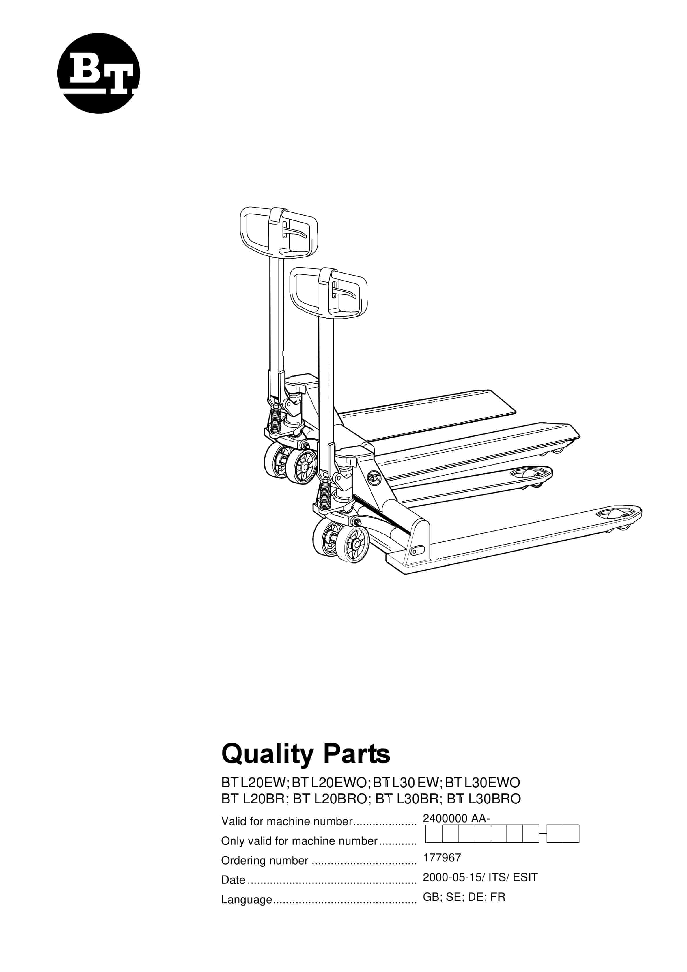
BT BTL20EW, BTL20EWO, BTL30EW, BTL30EWO, L20BR, L20BRO, L30BR, L30BRO Quality Parts 177967
$30.00

BT Parts Manual PDF
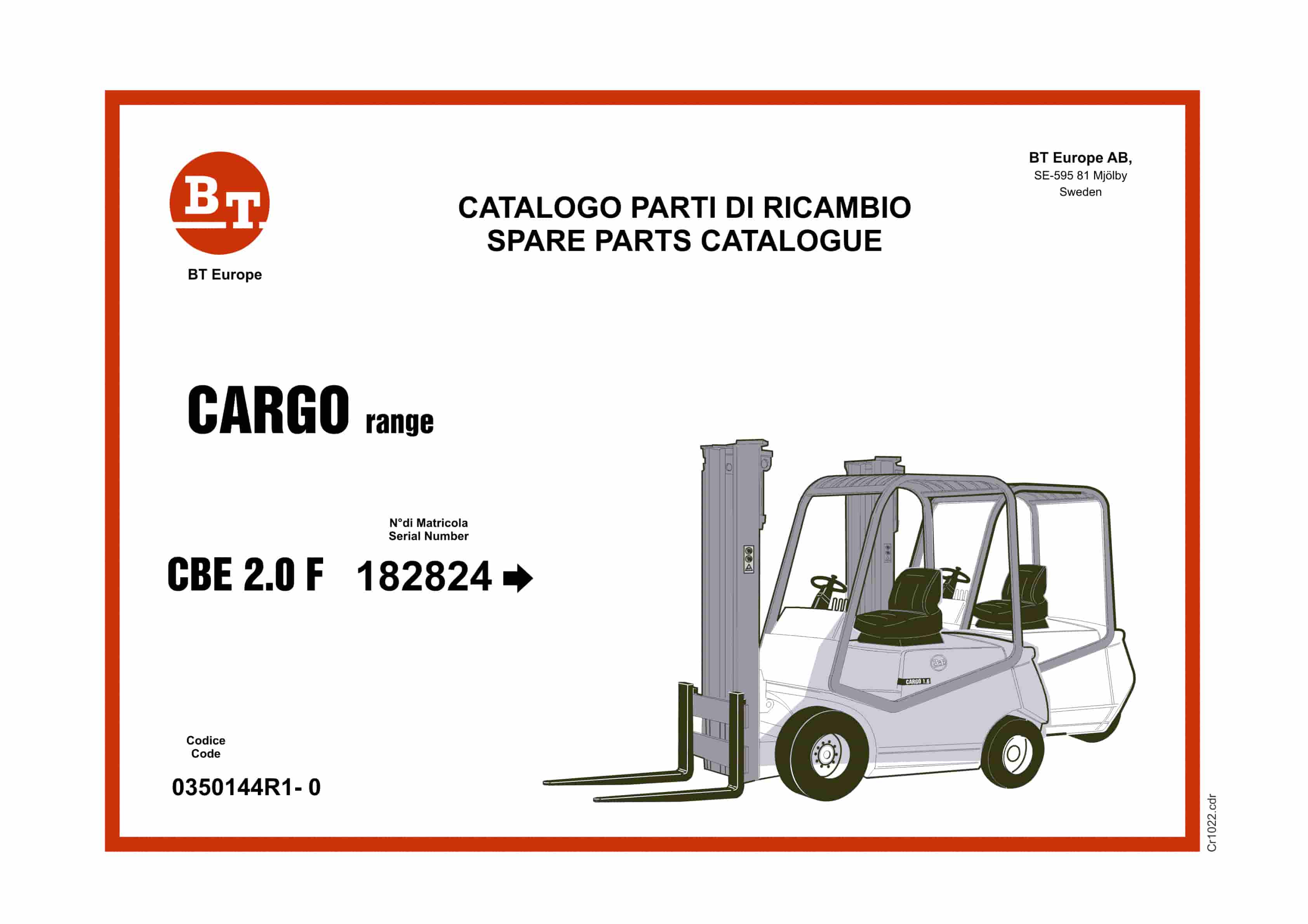
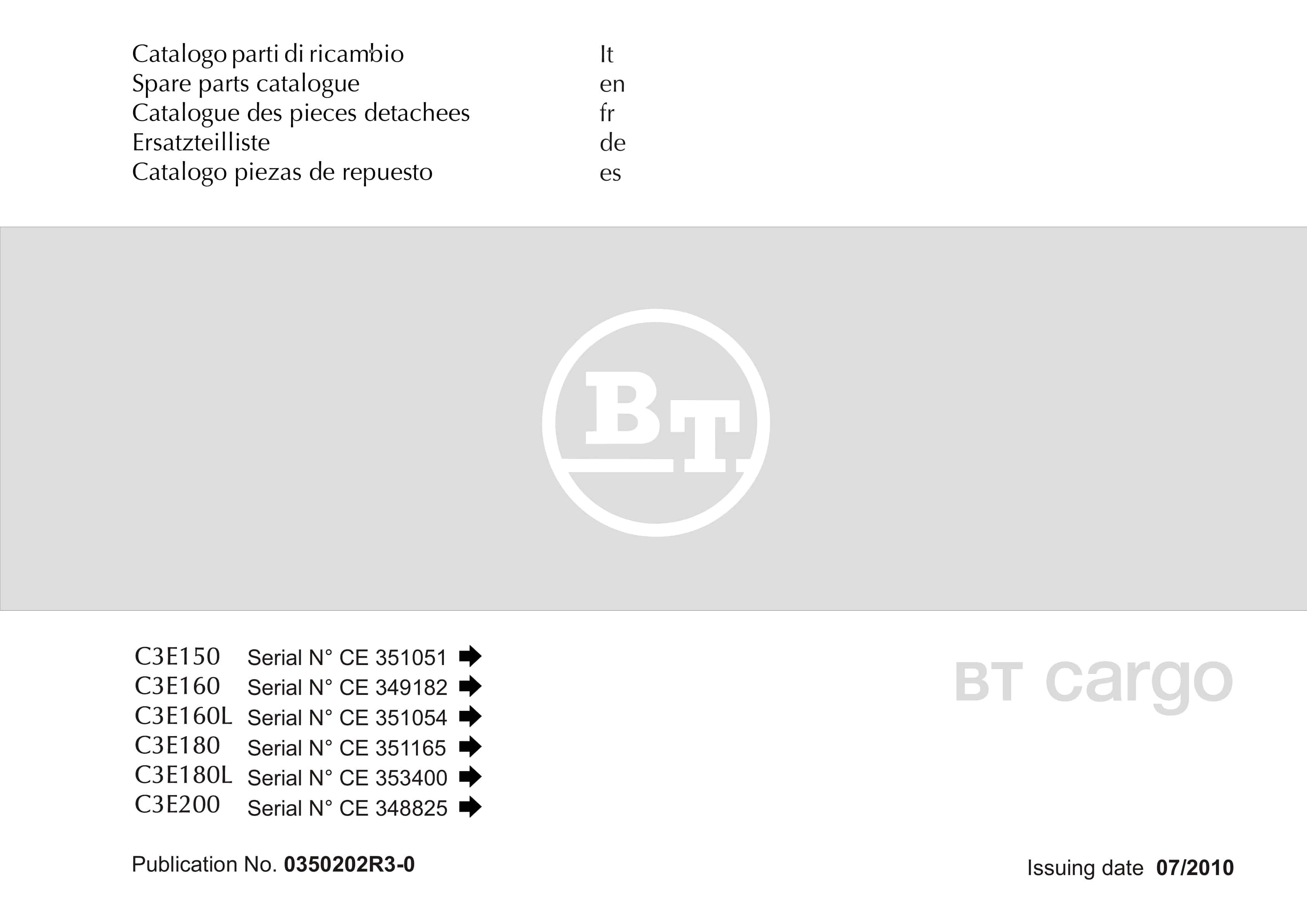
BT C3E150, C3E160, C3E160L, C3E180, C3E180L, C3E200 Spare Parts Catalog 0350202R3-0
$30.00


%20Quality%20Parts%20202994&url=https://ownersmanualpdf.net/docs/bt-canada-post-lr7a1-s-16d-quality-parts-202994/&media=https://ownersmanualpdf.net/wp-content/uploads/2025/12/bt-canada-post-lr7a1-s-16d-quality-parts-202994-1.jpg)