No products in the cart.
Return to shop
$30.00
BT Parts Manual PDF
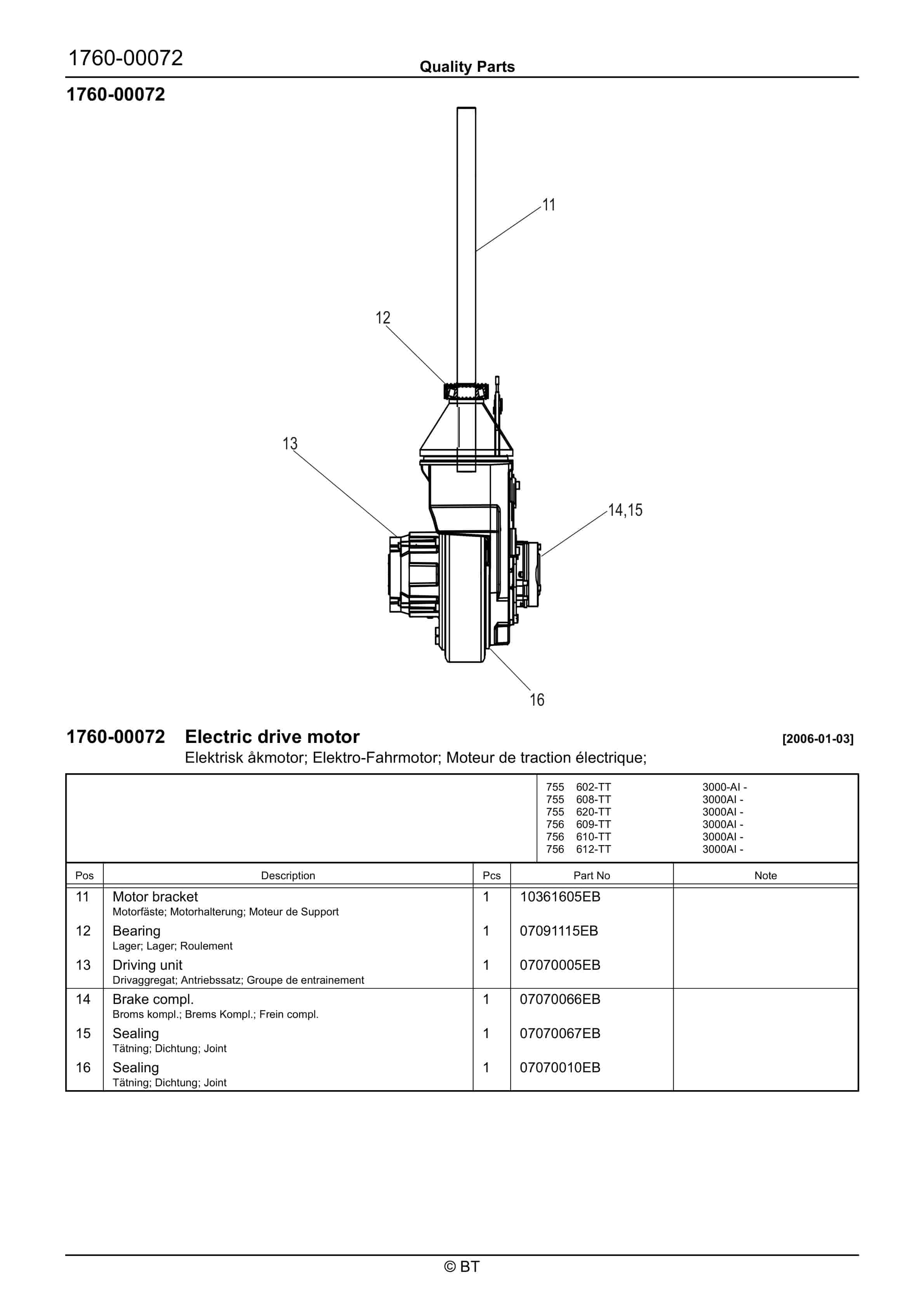
BT 602-TT, 608-TT, 609-TT, 610-TT, 612-TT, 620-TT Quality Parts 7501655
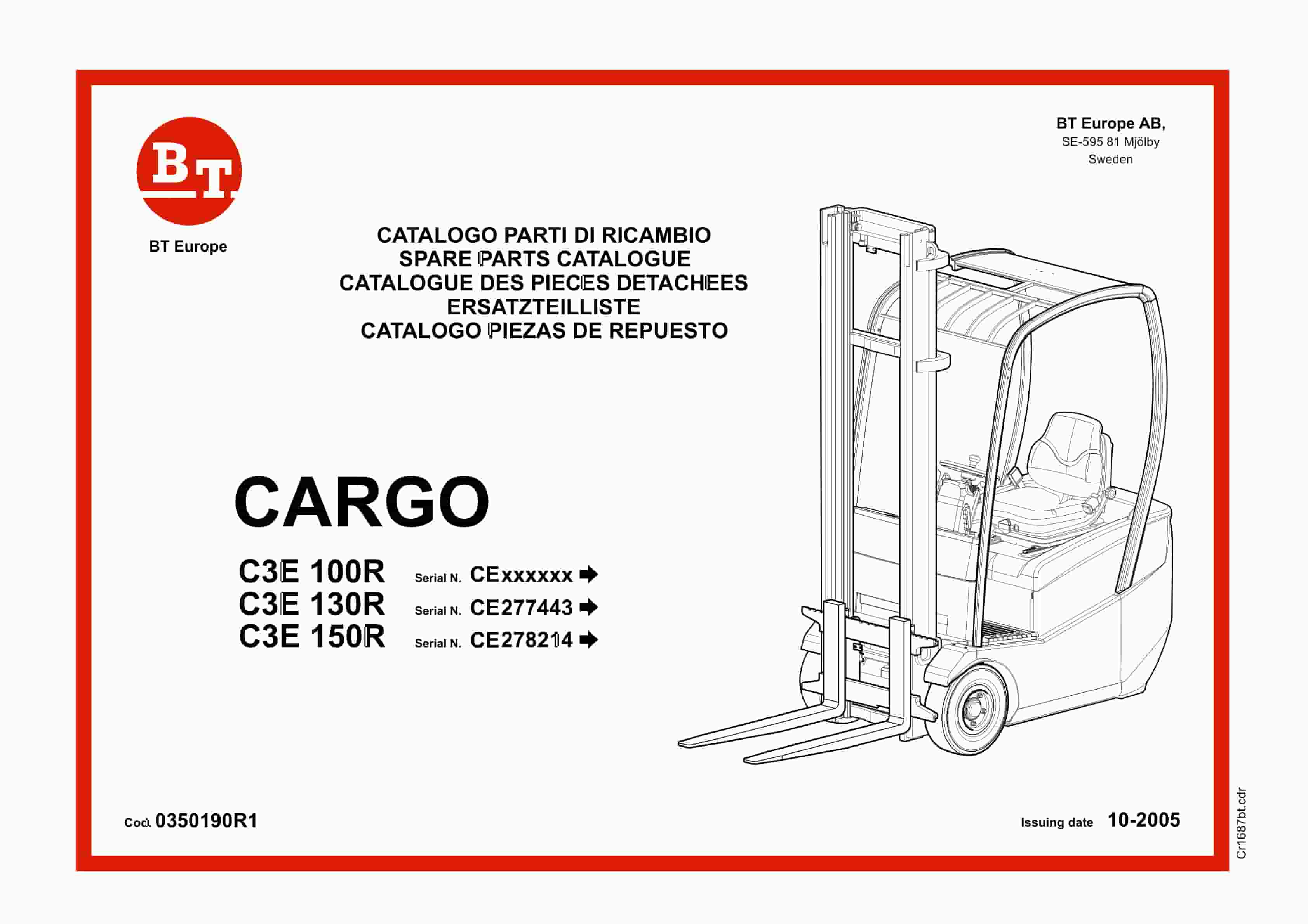
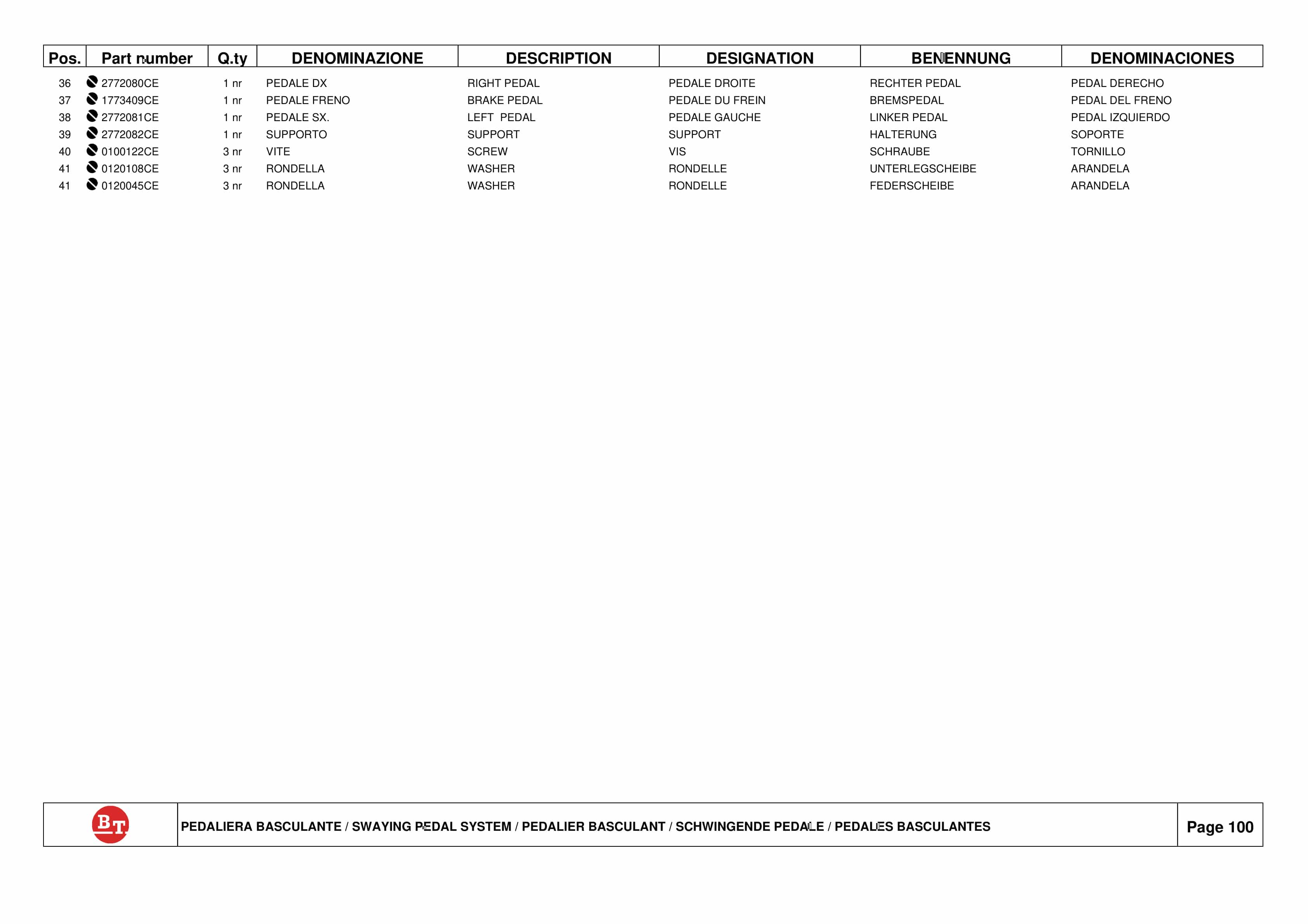
BT CARGO C3E 100R, C3E 130R, C3E 150R Spare Parts Catalog 0350190R1
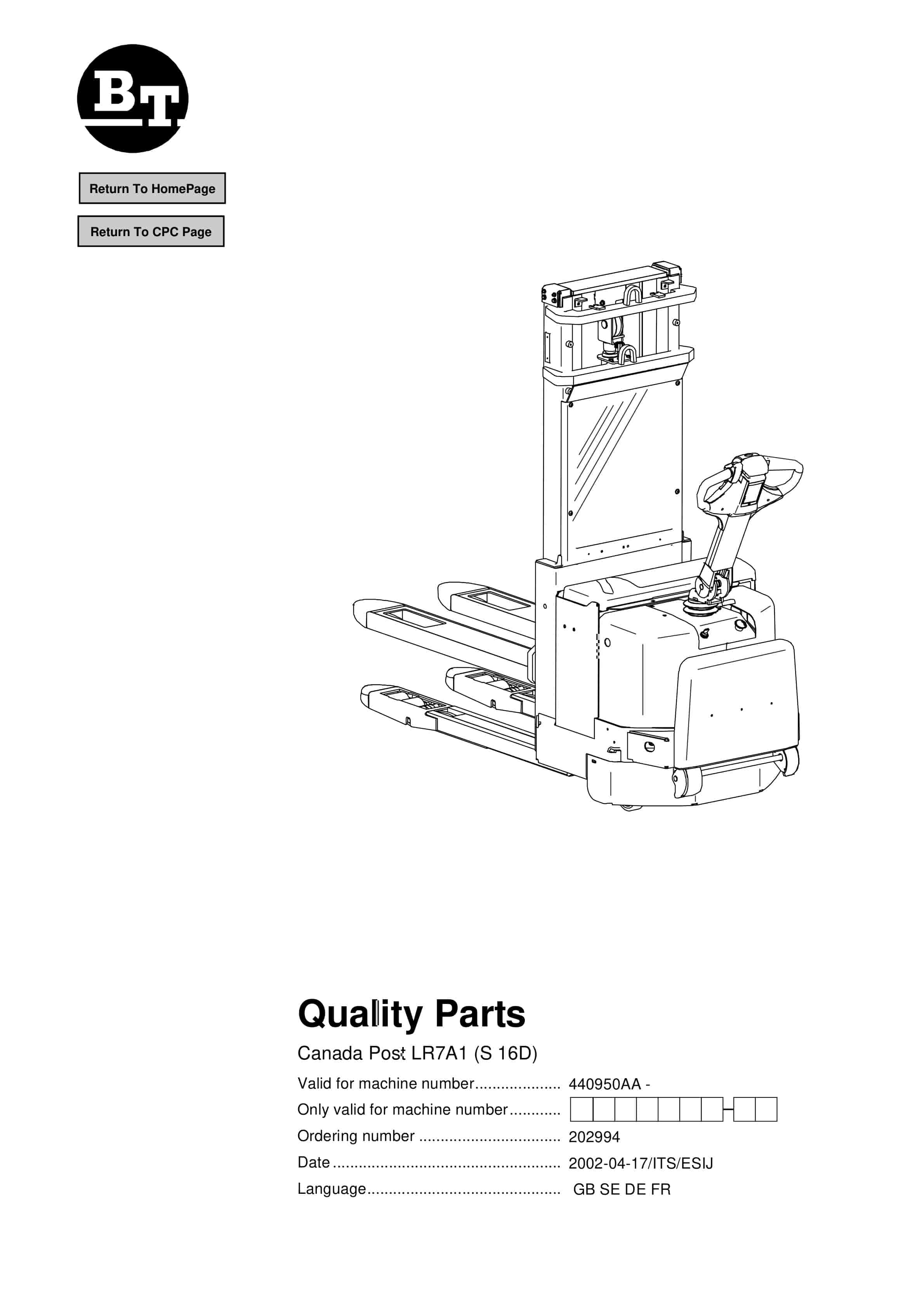
BT Canada Post LR7A1 (S 16D) Quality Parts 202994
BT Appendix II For Lift Pump And Motor Assembly
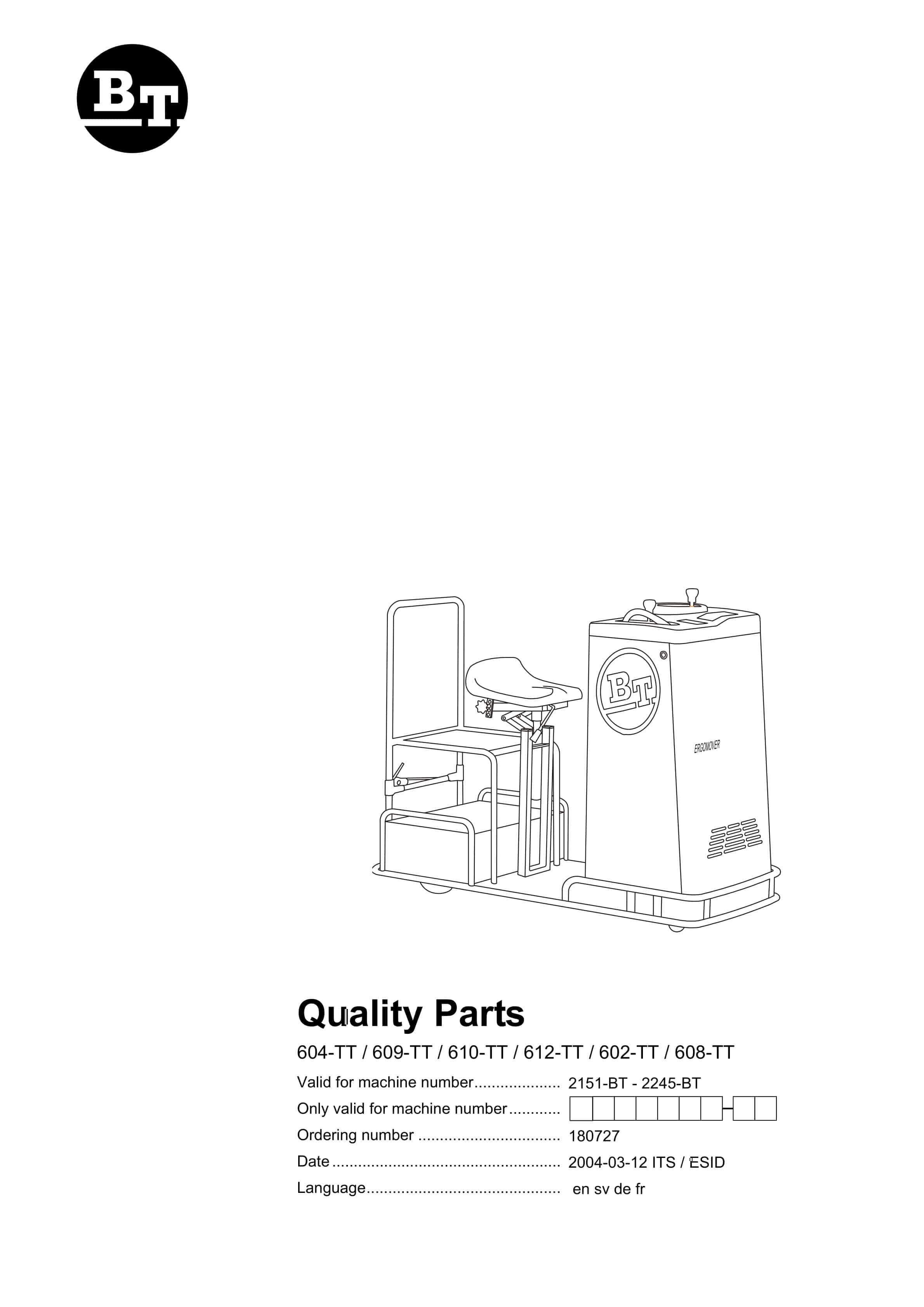
BT 604-TT, 609-TT, 610-TT, 612-TT, 602-TT, 608-TT Quality Parts 180727
BT CARGO E-Series CBE 15T Spare Parts Catalog 0350157R1-0
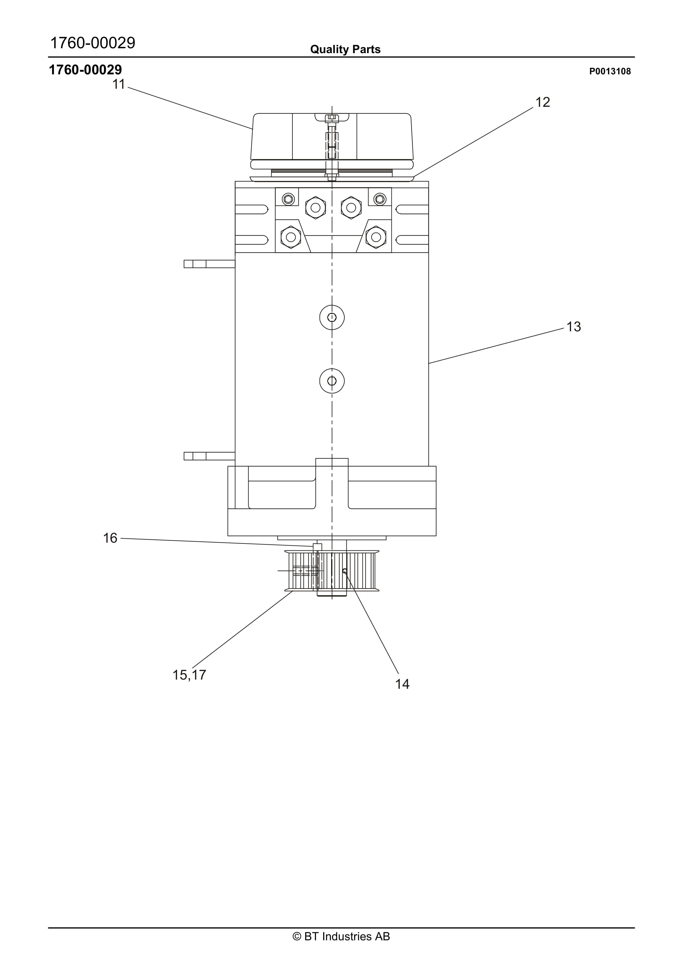
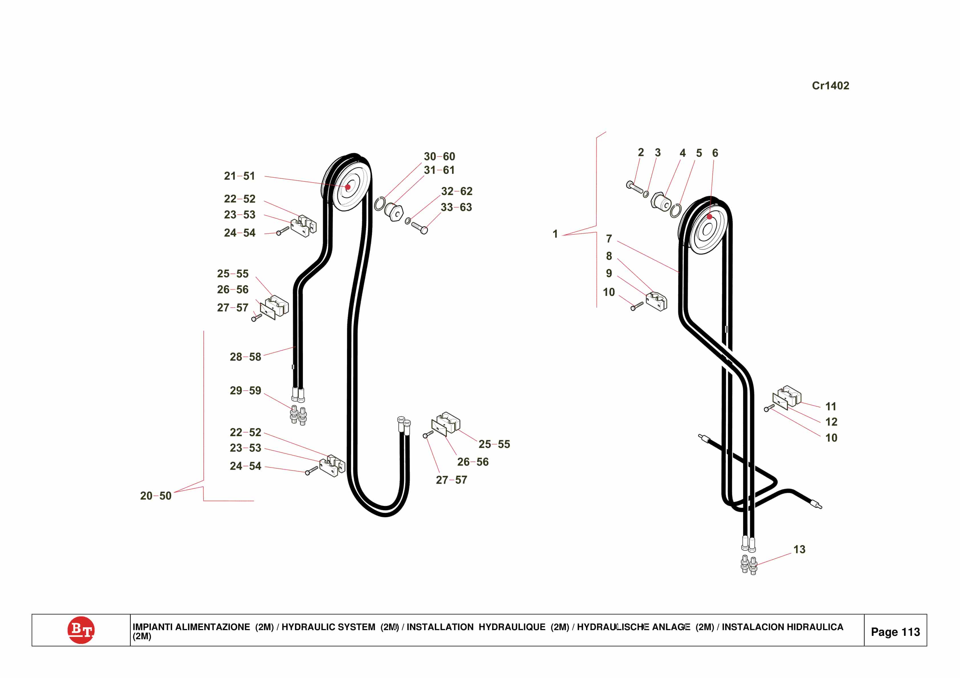
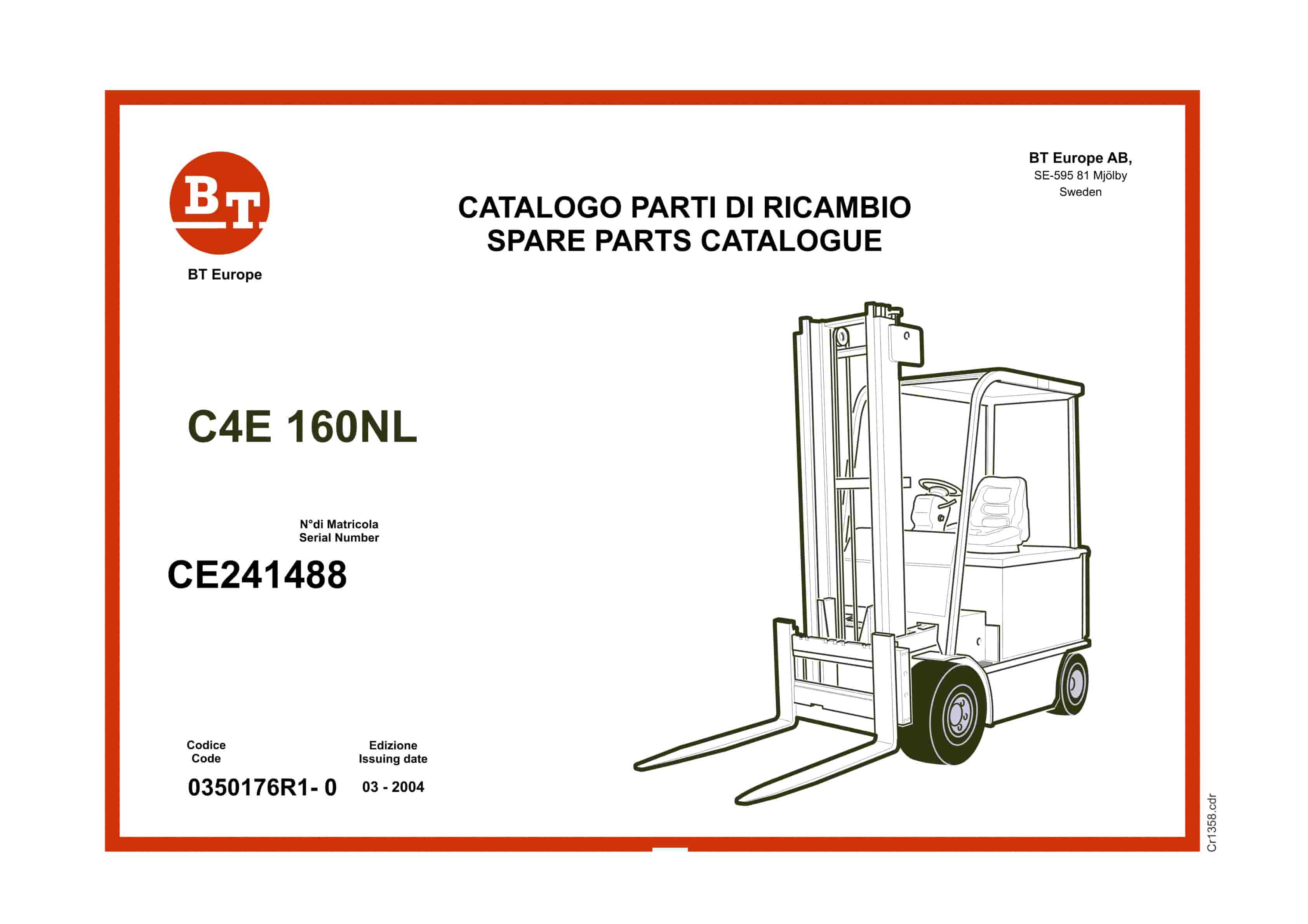
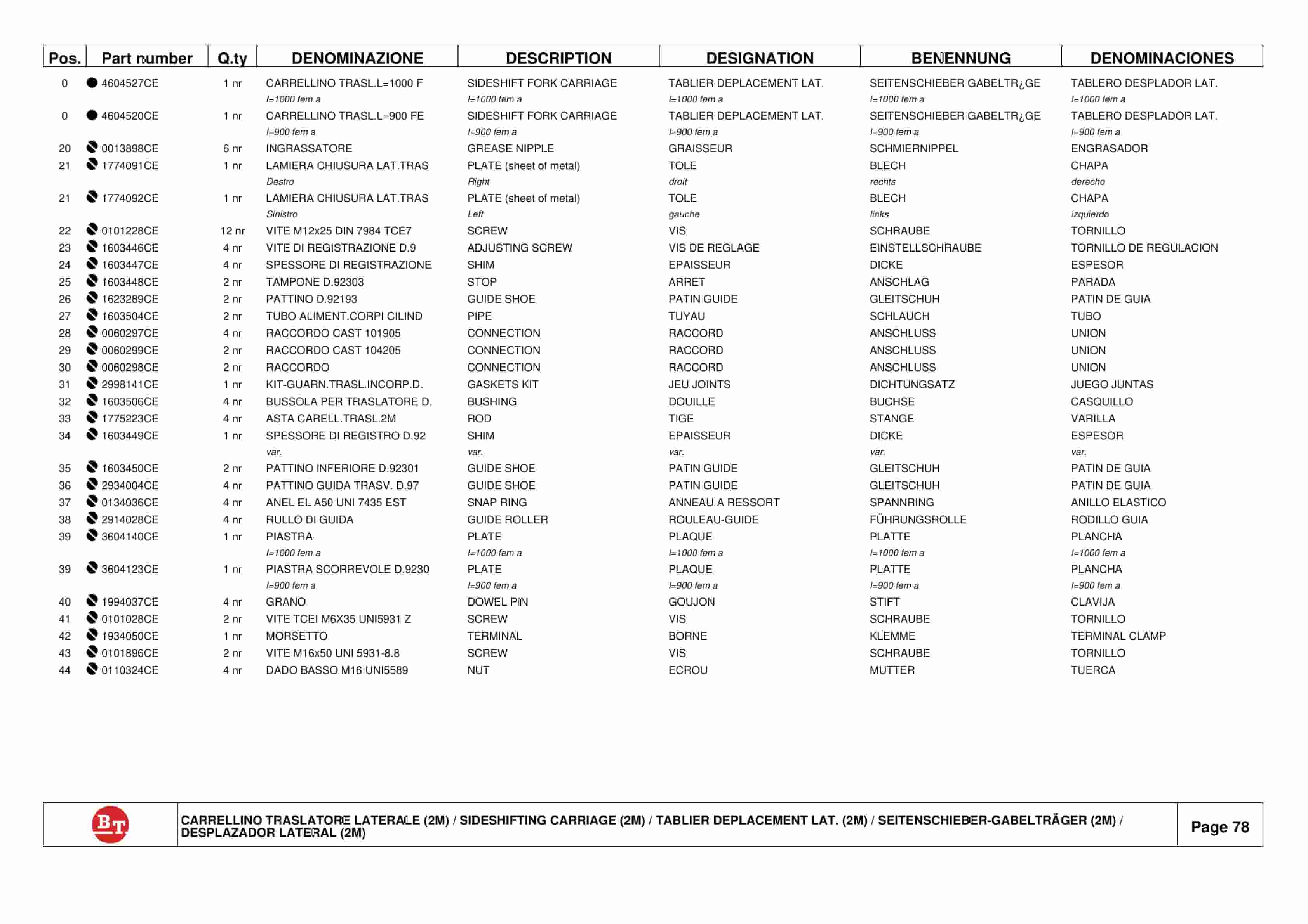
BT C4E 160NL Spare Parts Catalog 0350176R1-0
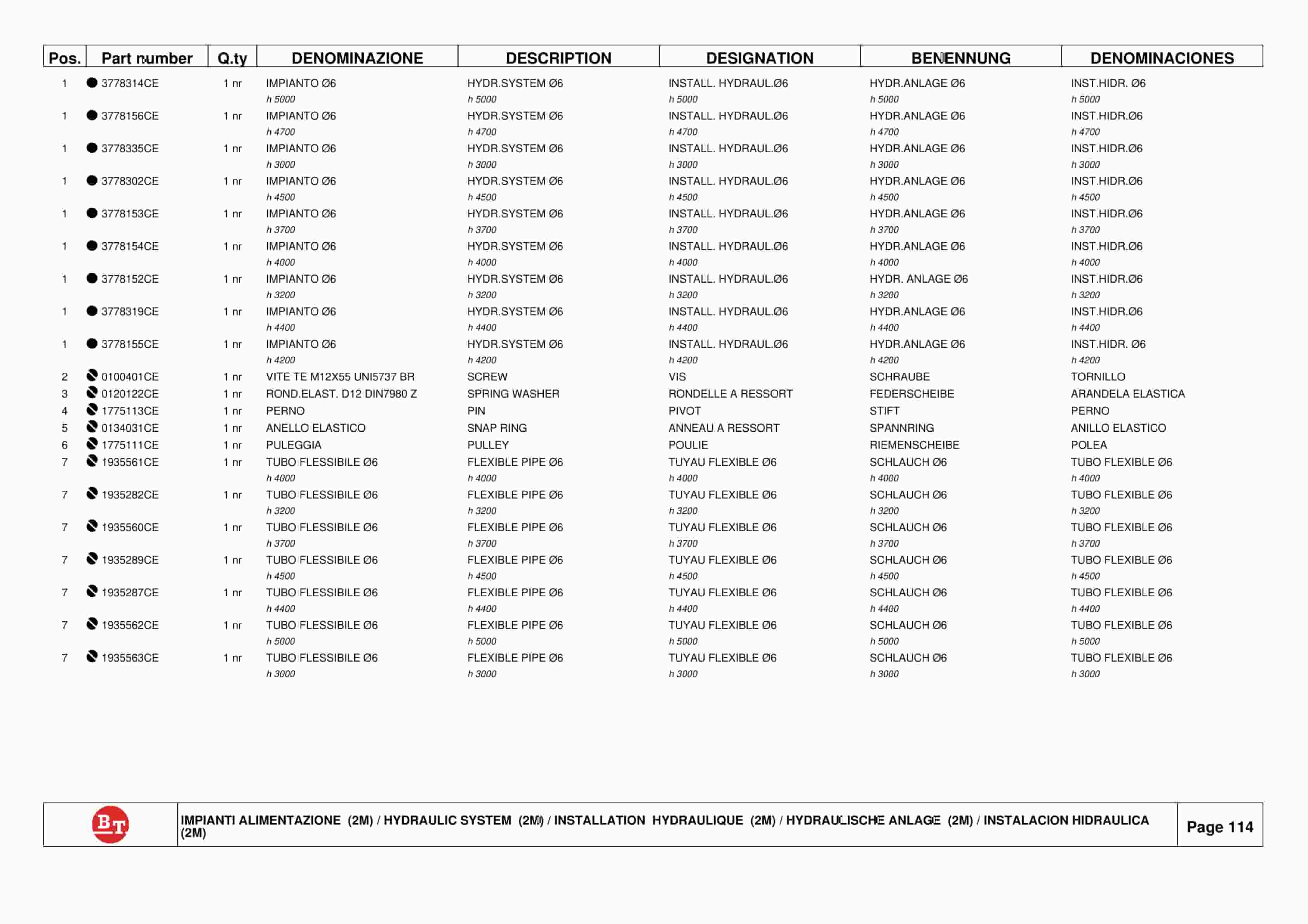
BT CARGO E-Series CBE 12F Spare Parts Catalog 0350163R1-0
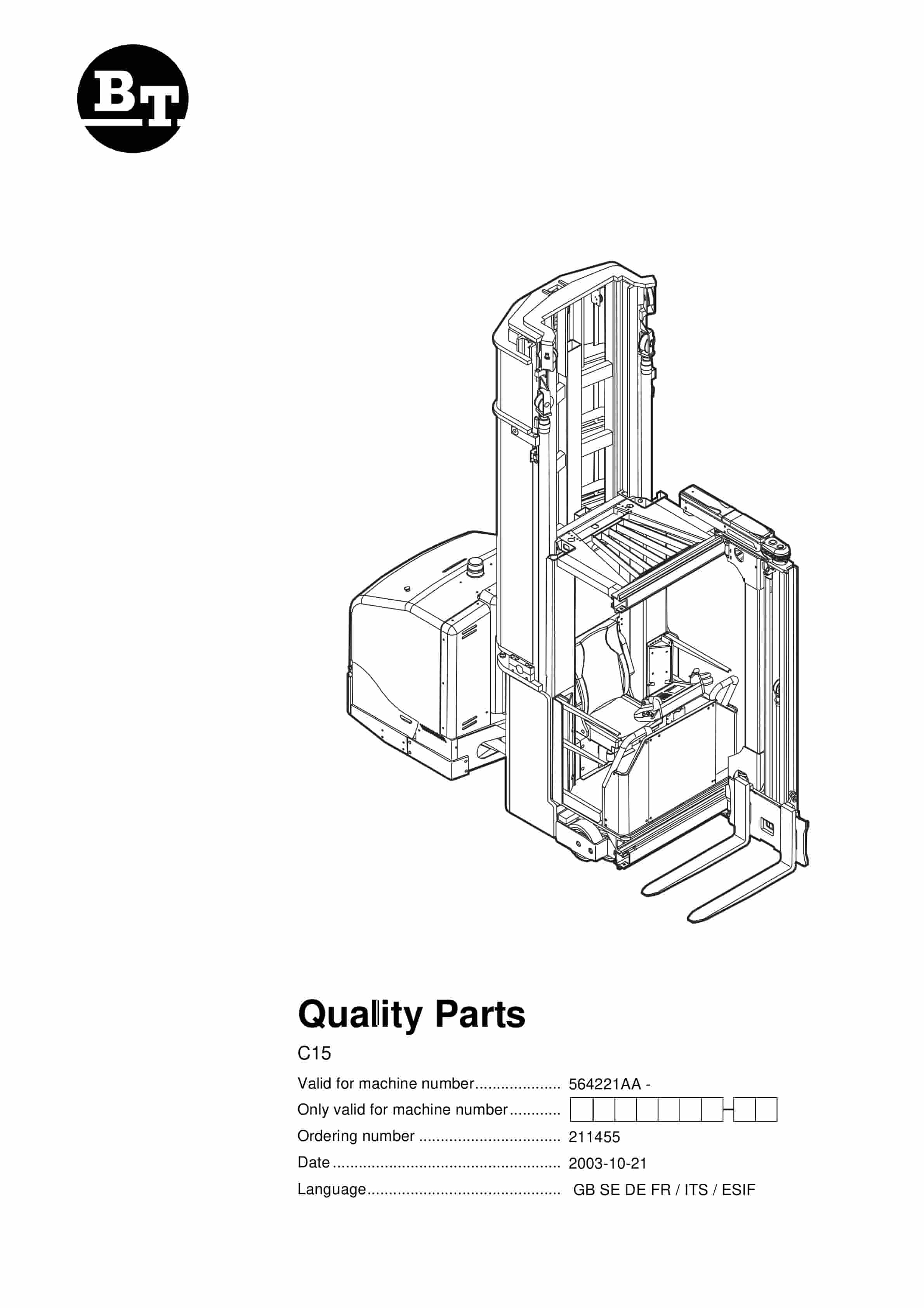
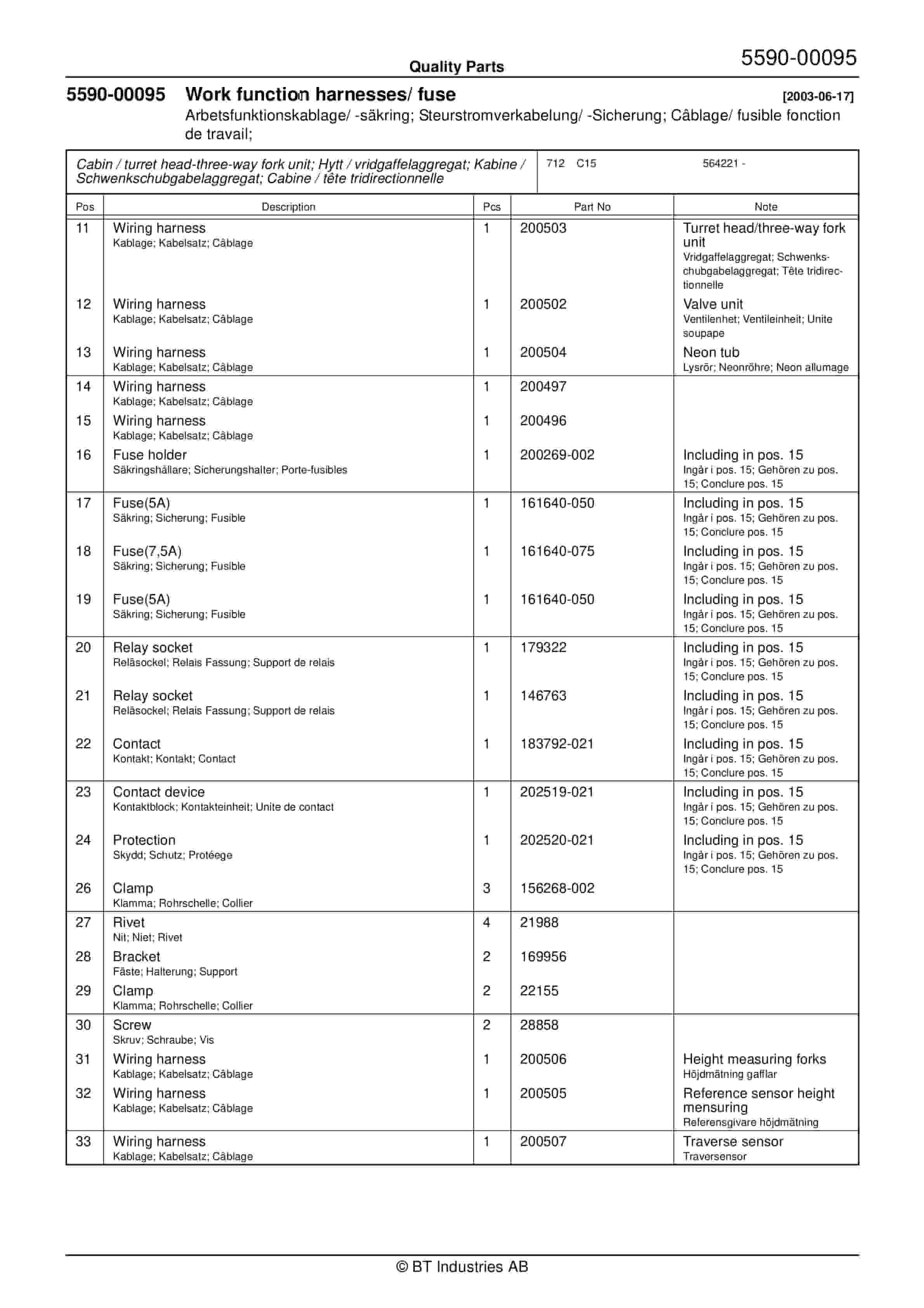
BT C15 564221AA Quality Parts 211455
BT 602-TT, 608-TT, 609-TT, 610-TT, 612-TT, 620-TT Quality Parts 241857


%20Quality%20Parts%20202994&url=https://ownersmanualpdf.net/docs/bt-canada-post-lr7a1-s-16d-quality-parts-202994/&media=https://ownersmanualpdf.net/wp-content/uploads/2025/12/bt-canada-post-lr7a1-s-16d-quality-parts-202994-1.jpg)