BT RS50BTH Electric Truck Parts Manual 301659-000
$30.00
- Type Of Manual: Parts Manual
- Manual ID: 301659-000
- : Parts Manual PDF
- Number of Pages: 98
- Size: 2.7MB
- Format: PDF
Category: BT Parts Manual PDF
-
Model List:
- RS50BTH Electric Truck
- 1. Front Cover
- 2. Parts Ordering Instructions
- 3. General Information
- 4. Alphabetical Index
- 5. Figure 0.1 Decals and Parts Assembly
- 6. Figure 0.2 Parts List Index
- 7. Figure 1.1 Transmission and Steering Installation
- 8. Figure 1.2 Drive Motor Brake Assembly
- 9. Figure 1.3 Transmission Assembly (40011-00) Part I
- 10. Figure 1.4 Transmission Assembly (40011-00) Part II
- 11. Figure 2.1 EV-100LX SCR Electrical Schematic
- 12. Figure 2.2 EV-100LX SCR Electrical Schematic Symbols
- 13. Figure 2.3 Wiring Harness Assembly
- 14. Figure 2.4 EV-100LX Power Component Wiring
- 15. Figure 2.5 EV-100LX TX SCR Control Panel Assembly (49399-00)
- 16. Figure 2.6 EV-100LX Contactor Panel Assembly Related Parts
- 17. Figure 2.7 EV-100LX Contactor Panel Assembly (41757-01)
- 18. Figure 2.8 EV-100LX SCR Forward Rearward Contactor Assembly (27692-00)
- 19. Figure 2.9 EV-100LX SCR 1A Contactor Assembly (27693-02)
- 20. Figure 2.10 EV-100LX SCR Auxiliary Pump Contactor Assembly (300073-000)
- 21. Figure 2.11 Power Connector Assembly (24 Volt, 49855-24)
- 22. Figure 2.12 Drive Motor Assembly, (27901-00, 5BT1326B235) G.E.
- 23. Figure 2.13 Auxiliary Pump Motor Assembly (300666-000, D-561371X8015A, OHIO)
- 24. Figure 3.1 Hydraulic Schematic
- 25. Figure 3.2 Hydraulic Schematic Symbols
- 26. Figure 3.3 Auxiliary Pump and Reservoir Assembly
- 27. Figure 3.4 Auxiliary Control Valve Assembly (41331-00)
- 28. Figure 3.5 Auxiliary Pump and Motor Assembly (300333-000)
- 29. Figure 3.6 Auxiliary Pump Assembly
- 30. Figure 3.7 Hydraulic Reservoir Assembly
- 31. Figure 3.8 Steering Control Valve Assembly (40102-01)
- 32. Figure 3.9 Steering Control Valve and Hose Assembly
- 33. Figure 3.10 Steering Cylinder Assembly (41544-00)
- 34. Figure 3.11 Clamp Cylinder and Related Parts
- 35. Figure 3.12 Clamp Cylinder Assembly (41228-00)
- 36. Figure 3.13 Brake Linkage and Cylinder Assembly
- 37. Figure 3.14 Brake Master Cylinder (41336-00)
- 38. Figure 3.15 Drive Motor Brake Cylinder (41337-00)
- 39. Figure 3.16 Idler Wheel Brake Cylinder (41338-00)
- 40. Figure 4.1 Shielding Assembly
- 41. Figure 4.2 Emergency Disconnect Assembly
- 42. Figure 4.3 Hand Clamp and Speed Control
- 43. Figure 4.4 Steering Control Assembly
- 44. Figure 4.5 Idler Wheel Installation
- 45. Figure 4.6 Idler Wheel Assembly
- 46. Figure 4.7 Main Frame and Load Wheel Assembly
- 47. Figure 10.1 Special Tools and Lubrications
- 48. Numerical Index
- 49. Back Cover
Rate this product
You may also like
BT Parts Manual PDF
BT 600-TT, 602-TT, 604-TT, 608-TT, 609-TT, 610-TT, 612-TT, 620-TT Quality Parts 208538
$30.00
BT Parts Manual PDF
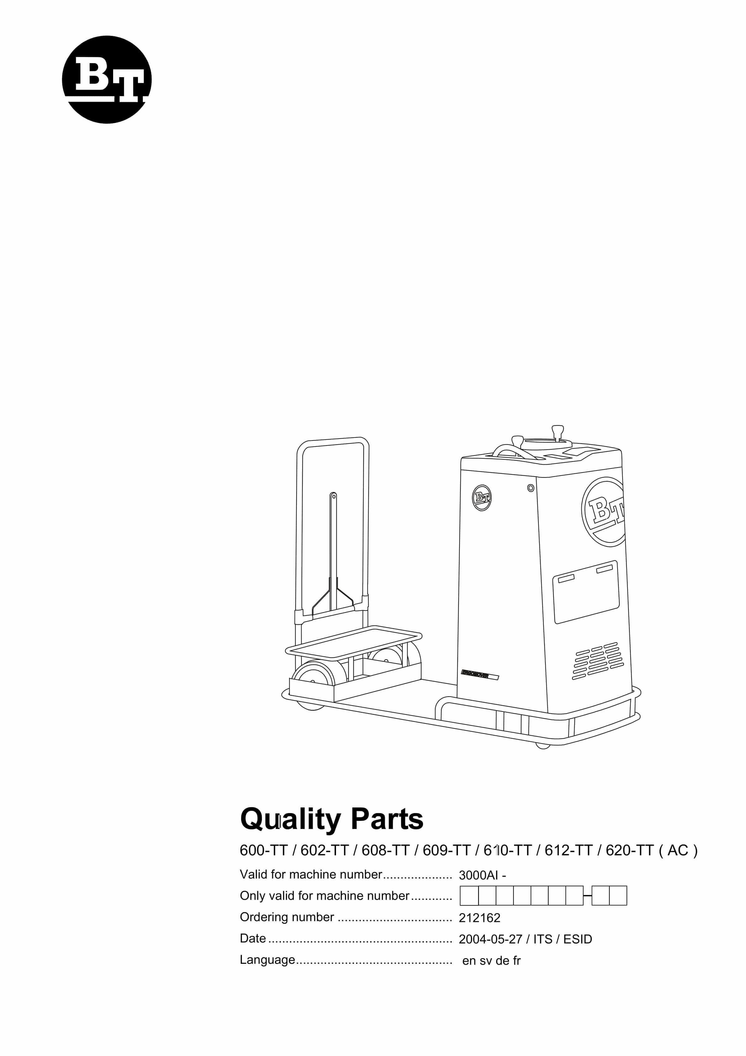
BT 600-TT, 602-TT, 608-TT, 609-TT, 610-TT, 612-TT, 620-TT (AC) Quality Parts 212162
$30.00
BT Parts Manual PDF
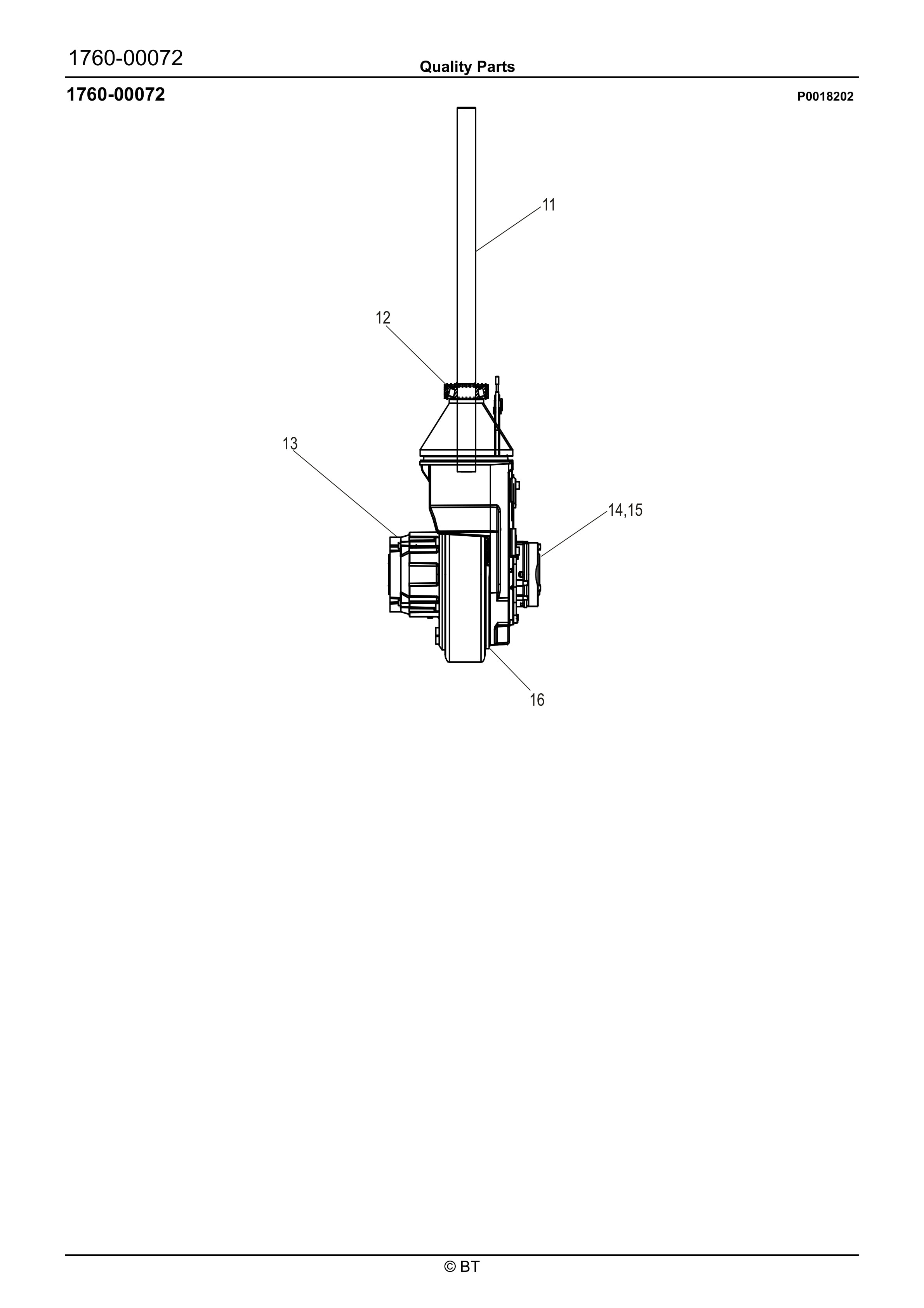
BT 602-TT, 608-TT, 609-TT, 610-TT, 612-TT, 620-TT Quality Parts 07904570EB
$30.00
BT Parts Manual PDF
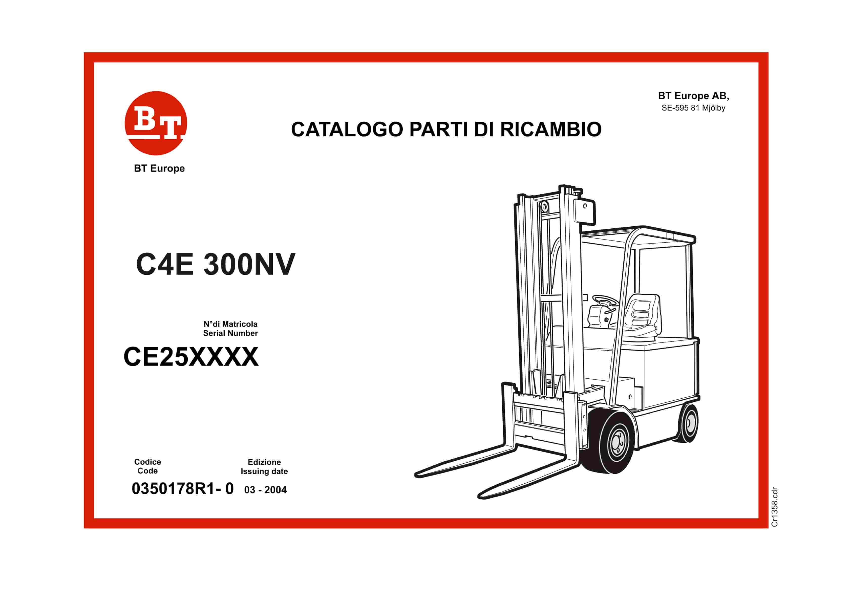
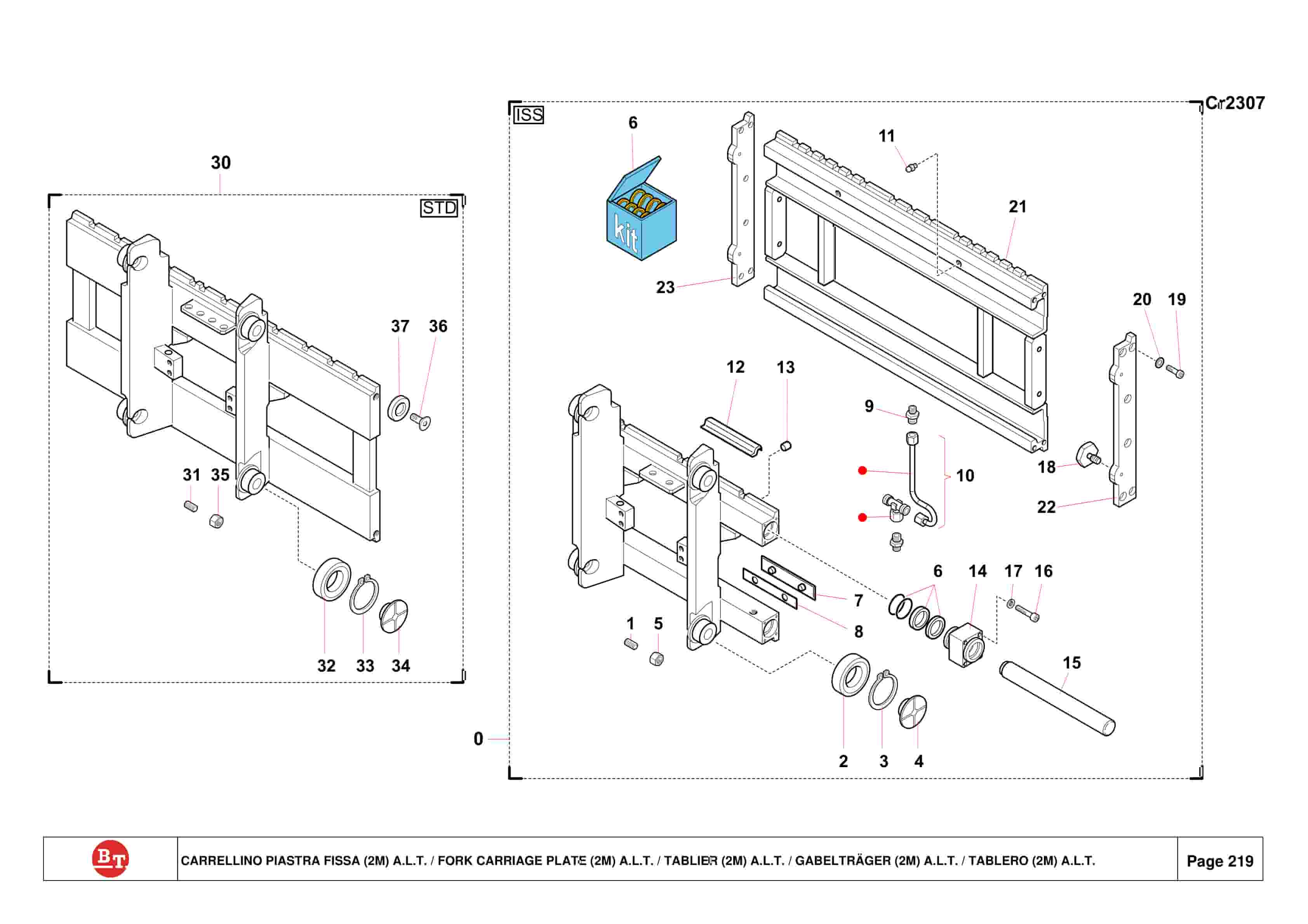
BT C3E150, C3E160, C3E160L, C3E180, C3E180L, C3E200 Spare Parts Catalog 0350202R3-0
$30.00


