BT SN-20, SN-30, SN-40 Electric Walkie Straddle Stacker Parts Manual 300380-001
$30.00
- Type Of Manual: Parts Manual
- Manual ID: 300380-001
- : Parts Manual PDF
- Number of Pages: 240
- Size: 4.2MB
- Format: PDF
Category: BT Parts Manual PDF
-
Model List:
- SN-20, SN-30, SN-40 Electric Walkie Straddle Stacker
- 1. Front Cover
- 2. Parts Ordering Instructions
- 3. General Information
- 4. Figure 0.1 Decals and Parts Assembly
- 5. Figure 0.2 Parts List Index
- 6. Figure 1.1 Transmission and Handle Assembly
- 7. Figure 1.2 Standard Control Handle Assembly
- 8. Figure 1.3 Thumb Control Handle Assembly
- 9. Figure 1.4 Transmission Assembly, Part 1
- 10. Figure 1.5 Single Disc Brake Transmission Assembly
- 11. Figure 1.6 Drive Motor Assembly
- 12. Figure 2.1 Resistor Electrical Schematic
- 13. Figure 2.2 Resistor Electrical Schematic Symbols
- 14. Figure 2.3 Resistor Control Wiring Harness Assembly
- 15. Figure 2.4 Resistor Power Component Wiring
- 16. Figure 2.5 Control Panel Assembly
- 17. Figure 2.6 Second Speed Contactor Assembly
- 18. Figure 2.7 Forward Rearward Contactor Assembly
- 19. Figure 2.8 Power Connector Assembly
- 20. Figure 2.9 Bosch Hydraulic Pump Motor Assembly
- 21. Figure 2.10 12 Volt Drive Motor Assembly
- 22. Figure 2.11 24 Volt Drive Motor Assembly
- 23. Figure 2.12 Pump Motor Assembly
- 24. Figure 2.13 Warning Light Assembly
- 25. SN-20 Hydraulic Section
- 25.1. Figure 3.1 SN-20 Two Stage Hydraulic Schematic
- 25.2. Figure 3.2 SN-20 Two Stage Hydraulic Schematic Symbols
- 25.3. Figure 3.3 SN-20 12/24 Volt Two Stage Mast Hydraulic System
- 25.4. Figure 3.4 SN-20 12/24 Volt Reservoir and Pump Assembly
- 25.5. Figure 3.5 SN-20 Bosch Pump and Motor Assembly
- 25.6. Figure 3.6 SN-20 Lift Cylinder Assembly
- 25.7. Figure 3.7 SN-20 Three Stage Hydraulic Schematic
- 25.8. Figure 3.8 SN-20 Three Stage Hydraulic Schematic Symbols
- 25.9. Figure 3.9 SN-20 12/24 Volt Three Stage Mast Hydraulic System
- 25.10. Figure 3.10 SN-20 12/24 Volt Reservoir and Pump Assembly
- 25.11. Figure 3.11 SN-20 Bosch Pump and Motor Assembly
- 25.12. Figure 3.12 SN-20 Three Stage Freelift Cylinder Assembly
- 25.13. Figure 3.13 SN-20 Three Stage Freelift Cylinder Assembly
- 26. SN-30 Hydraulic Section
- 26.1. Figure 3.14 SN-30 Two Stage Hydraulic Schematic
- 26.2. Figure 3.15 SN-30 Two Stage Hydraulic Schematic Symbols
- 26.3. Figure 3.16 SN-30 12 Volt Two Stage Mast Hydraulic System
- 26.4. Figure 3.17 SN-30 Hydraulic Pump and Valve Installation, 24 Volt
- 26.5. Figure 3.18 SN-30 12 Volt Reservoir and Pump Assembly
- 26.6. Figure 3.19 SN-30 Two Stage Mast Bosch Pump and Motor Assembly
- 26.7. Figure 3.20 SN-30 Two Stage Lift Cylinder Assembly
- 26.8. Figure 3.21 SN-30 Two Stage Hydraulic Reservoir Assembly
- 26.9. Figure 3.22 SN-30 24 Volt Lift Pump and Motor Assembly
- 26.10. Figure 3.23 SN-30 24 Volt Lift Pump Assembly
- 26.11. Figure 3.24 SN-30 Three Stage Hydraulic Schematic
- 26.12. Figure 3.26 SN-30 12 Volt Three Stage Mast Hydraulic System
- 26.13. Figure 3.27 SN-30 24 Volt Three Stage Hydraulic System, Part 1
- 26.14. Figure 3.28 SN-30 24 Volt Three Stage Mast Hydraulic System, Part 2
- 26.15. Figure 3.29 SN-30 12 Volt Reservoir and Pump Assembly
- 26.16. Figure 3.30 SN-30 Bosch Pump and Motor Assembly
- 26.17. Figure 3.31 SN-30 Three Stage Freelift Cylinder Assembly
- 26.18. Figure 3.32 SN-30 Three Stage Freelift Cylinder Assembly
- 26.19. Figure 3.33 SN-30 24 Volt Three Stage Hydraulic Reservoir Assembly
- 26.20. Figure 3.34 SN-30 24 Volt Lift Pump and Motor Assembly
- 26.21. Figure 3.35 SN-30 Lift Pump Assembly
- 26.22. Figure 3.36 SN-30 Manual Hydraulic Schematic
- 26.23. Figure 3.37 SN-30 Manual Hydraulic Schematic Symbols
- 26.24. Figure 3.38 SN-30 Manual Hydraulic System – Part 1
- 26.25. Figure 3.39 SN-30 Manual Hydraulic System – Part 2
- 26.26. Figure 3.40 SN-30 Manual Lift Two Stage Lift Cylinder and Related Parts
- 26.27. Figure 3.41 SN-30 Manual Lift Three Stage Lift Cylinders and Related Parts
- 26.28. Figure 3.42 SN-30 Manual Two/Three Spool Control Valve Assembly
- 26.29. Figure 3.43 SN-30 Manual Lift Pump and Motor Assembly
- 26.30. Figure 3.44 SN-30 Manual Lift Pump Assembly
- 26.31. Figure 3.45 SN-30 Manual Lift Hydraulic Reservoir Assembly
- 26.32. Figure 3.46 SN-30 Manual Lift Two Stage Cylinder Assembly
- 26.33. Figure 3.48 SN-30 Manual Lift Three Stage Freelift Cylinder Assembly
- 26.34. Figure 3.47 SN-30 Manual Lift Three Stage Freelift Cylinder Assembly
- 27. SN-40 Hydraulic Section
- 27.1. Figure 3.49 SN-40 Two Stage Hydraulic Schematic
- 27.2. Figure 3.50 SN-40 Two Stage Hydraulic Schematic Symbols
- 27.3. Figure 3.51 SN-40 Two Stage Hydraulic System – Part 1
- 27.4. Figure 3.52 SN-40 Two Stage Hydraulic System – Part 2
- 27.5. Figure 3.53 SN-40 Two Stage Lift Cylinder and Related Parts
- 27.6. Figure 3.54 SN-40 Two/Three Spool Control Valve Assembly
- 27.7. Figure 3.55 SN-40 Lift Pump and Motor Assembly
- 27.8. Figure 3.56 SN-40 Lift Pump Assembly
- 27.9. Figure 3.57 SN-40 Hydraulic Reservoir Assembly
- 27.10. Figure 3.58 SN-40 Two Stage Lift Cylinder Assembly
- 27.11. Figure 3.59 SN-40 Three Stage Hydraulic Schematic
- 27.12. Figure 3.60 SN-40 Three Stage Hydraulic Schematic Symbols
- 27.13. Figure 3.61 SN-40 Three Stage Hydraulic System – Part 1
- 27.14. Figure 3.62 SN-40 Three Stage Hydraulic System – Part 2
- 27.15. Figure 3.63 SN-40 Three Stage Lift Cylinders and Related Parts
- 27.16. Figure 3.64 SN-40 Two/Three Spool Control Valve Assembly
- 27.17. Figure 3.65 SN-40 Lift Pump and Motor Assembly
- 27.18. Figure 3.66 SN-40 Lift Pump Assembly
- 27.19. Figure 3.67 SN-40 Hydraulic Reservoir Assembly
- 27.20. Figure 3.68 SN-40 Three Stage Staging Cylinder Assembly
- 27.21. Figure 3.69 SN-40 Three Stage Freelift Cylinder Assembly
- 28. Figure 4.1 Shielding Assembly
- 29. Figure 4.2 Main Frame and Load Wheel Installation
- 30. Figure 4.3 Caster Assembly
- 31. Figure 4.4 Two/Three Spool Control Valve Mounting Assembly
- 32. Figure 4.5 Pallet Centering Device
- 33. Figure 5.1 SN-20/30 Two Stage Mast Installation
- 34. Figure 5.2 SN-20/30 Two Stage Outer Column Assembly (Frame)
- 35. Figure 5.3 SN-20/30 Two Stage Inner Column Assembly
- 36. Figure 5.4 SN-20/30 Two Stage Mast Cylinder and Related Parts
- 37. Figure 5.5 SN-20/30 Two Stage Mast Lift Frame and Load Backrest Assembly
- 38. Figure 5.6 SN-20/30 Two Stage Fork Assembly
- 39. Figure 5.7 SN-20/30 Three Stage Mast Installation
- 40. Figure 5.8 SN-20/30 Three Stage Mast Outer Column Assembly
- 41. Figure 5.9 SN-20/30 Three Stage Mast Intermediate Column Assembly
- 42. Figure 5.10 SN-20/30 Three Stage Mast Inner Column Assembly
- 43. Figure 5.11 SN-20/30 Three Stage Mast Freelift Cylinder and Related Parts
- 44. Figure 5.12 SN-20/30 Three Stage Mast Lift Frame and Backrest Assembly
- 45. Figure 5.13 SN-20/30 Three Stage Fork Assembly
- 46. Figure 5.14 SN-40 Two Stage Mast Installation
- 47. Figure 5.15 SN-40 Two Stage Mast Outer Column Assembly
- 48. Figure 5.16 SN-40 Two Stage Mast Inner Column Assembly
- 49. Figure 5.17 SN-40 Two Stage Mast Cylinder and Related Parts
- 50. Figure 5.18 SN-40 Two Stage Mast Lift Frame and Load Backrest Assembly
- 51. Figure 5.19 SN-40 Two Stage Fork Assembly
- 52. Figure 5.20 SN-40 Three Stage Mast Installation
- 53. Figure 5.21 SN-40 Three Stage Mast Outer Column Assembly
- 54. Figure 5.22 SN-40 Three Stage Mast Intermediate Column Assembly
- 55. Figure 5.23 SN-40 Three Stage Mast Inner Column Assembly
- 56. Figure 5.24 SN-40 Three Stage Mast Freelift Cylinder Installation
- 57. Figure 5.25 SN-40 Three Stage Mast Lift Frame and Load Backrest Assembly
- 58. Figure 5.26 SN-40 Three Stage Fork Assembly
- 59. Figure 7.1 Special Tools and Lubrications
- 60. Back Cover
Rate this product
You may also like
BT Parts Manual PDF
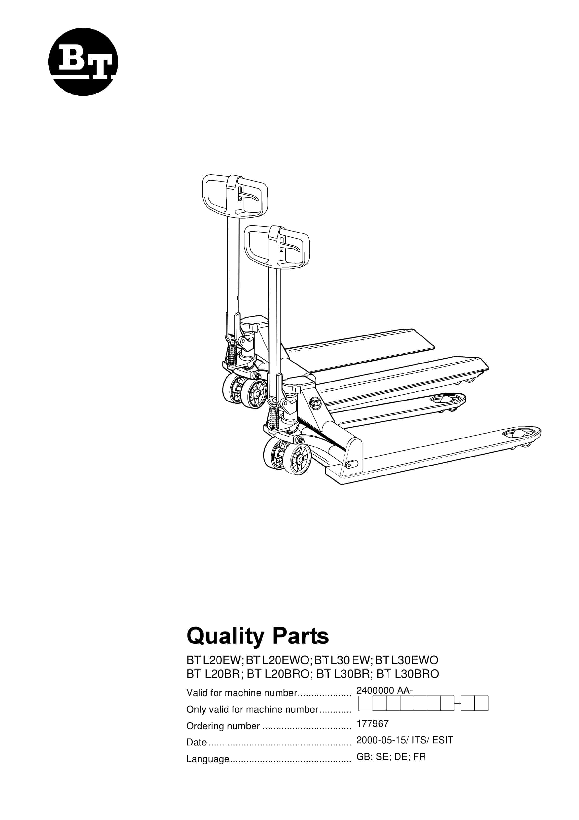
BT BTL20EW, BTL20EWO, BTL30EW, BTL30EWO, L20BR, L20BRO, L30BR, L30BRO Quality Parts 177967
$30.00
BT Parts Manual PDF
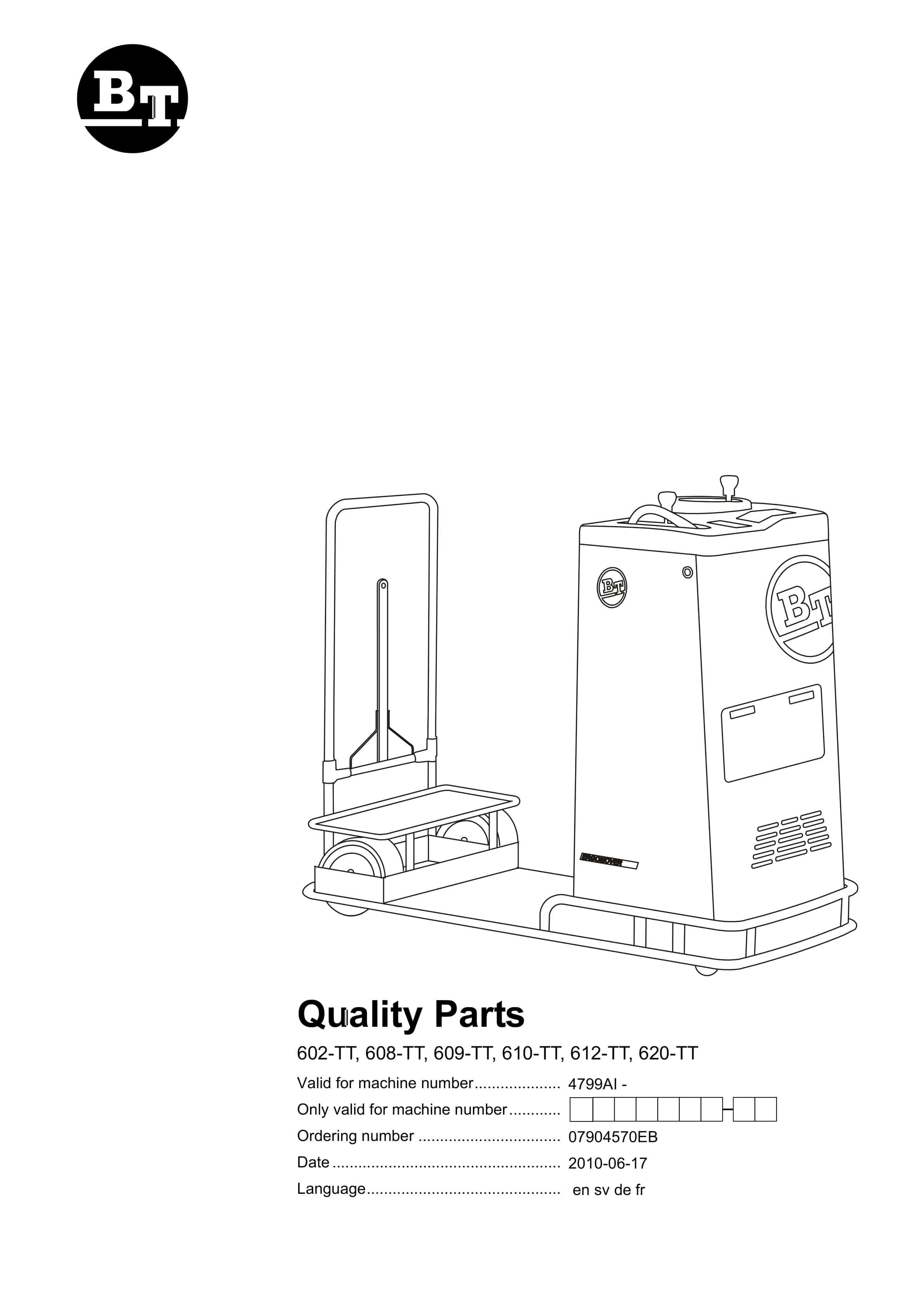
BT 602-TT, 608-TT, 609-TT, 610-TT, 612-TT, 620-TT Quality Parts 07904570EB
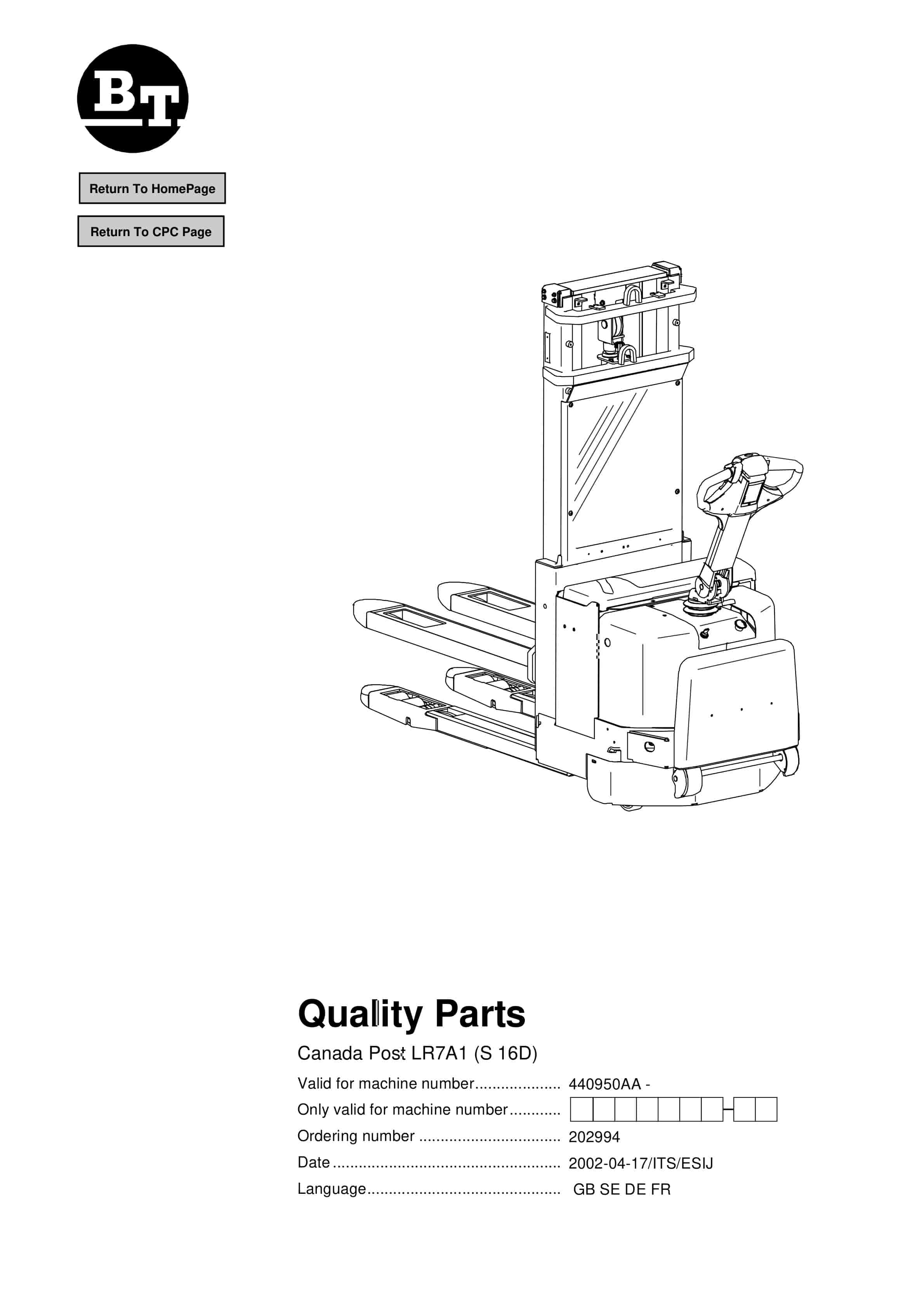
$30.00


