No products in the cart.
Return to shop
$30.00
BT Parts Manual PDF
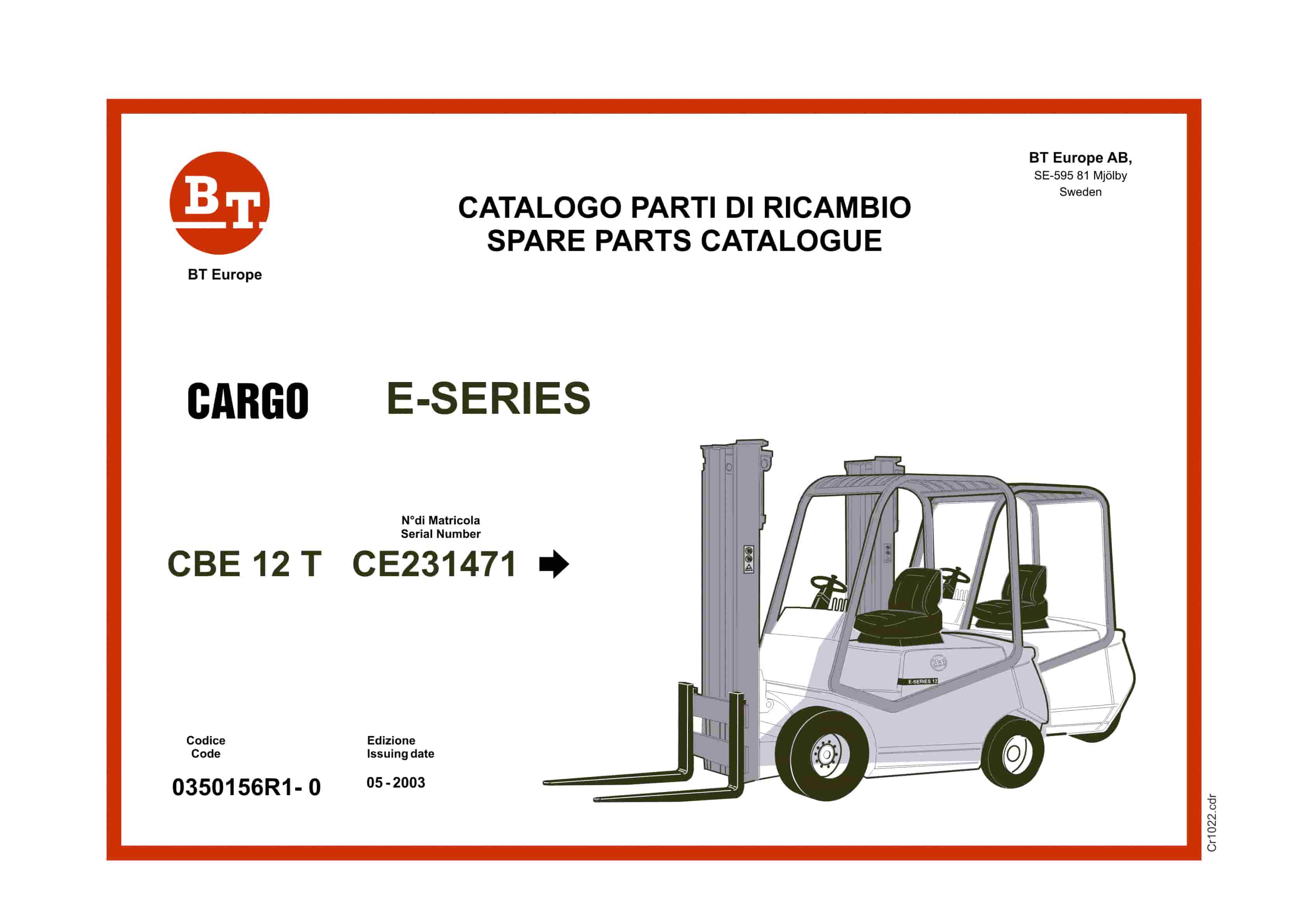
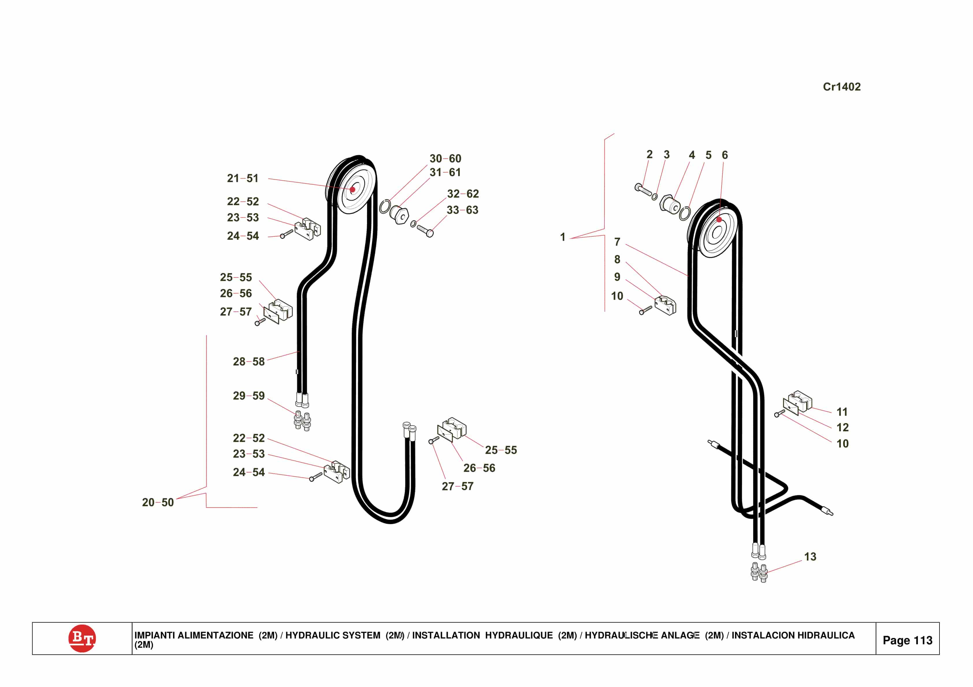
BT CARGO E-Series CBE 12T Spare Parts Catalog 0350156R1-0
BT Appendix II For Lift Pump And Motor Assembly
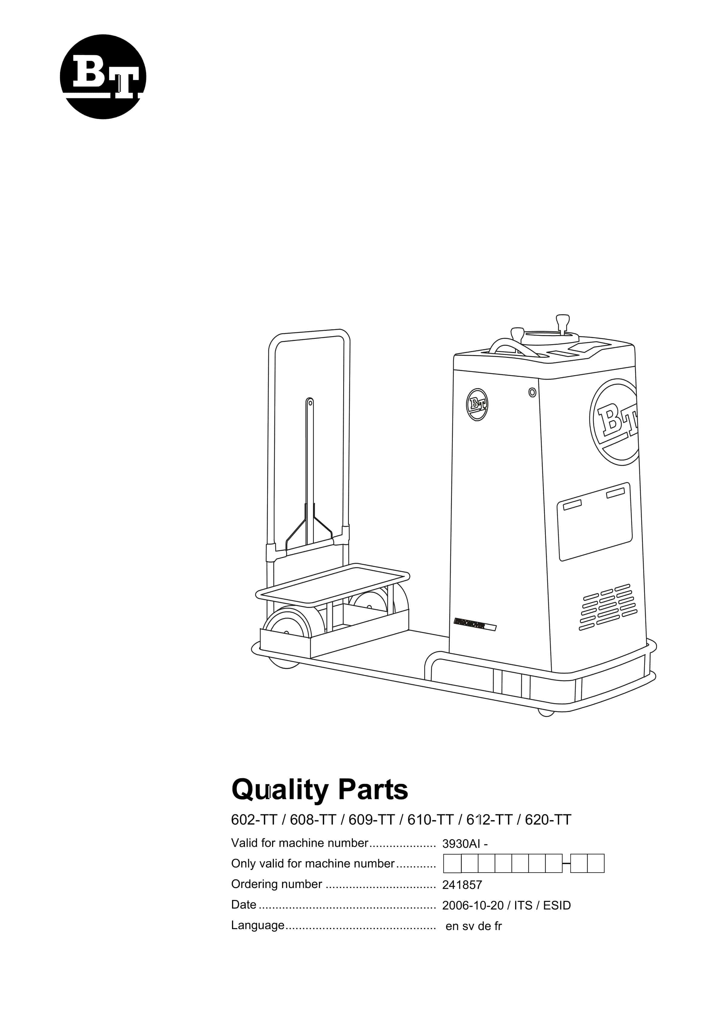
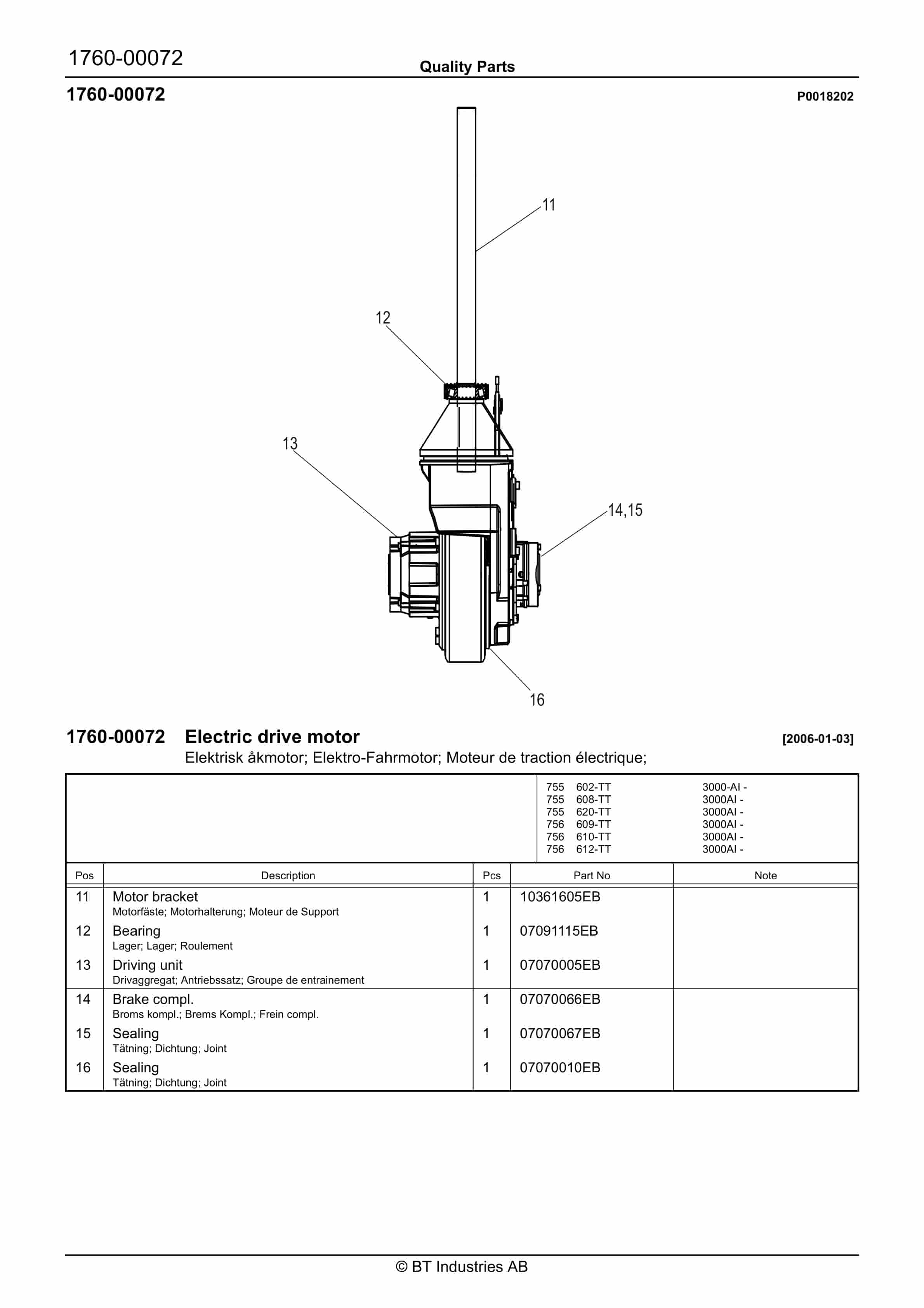
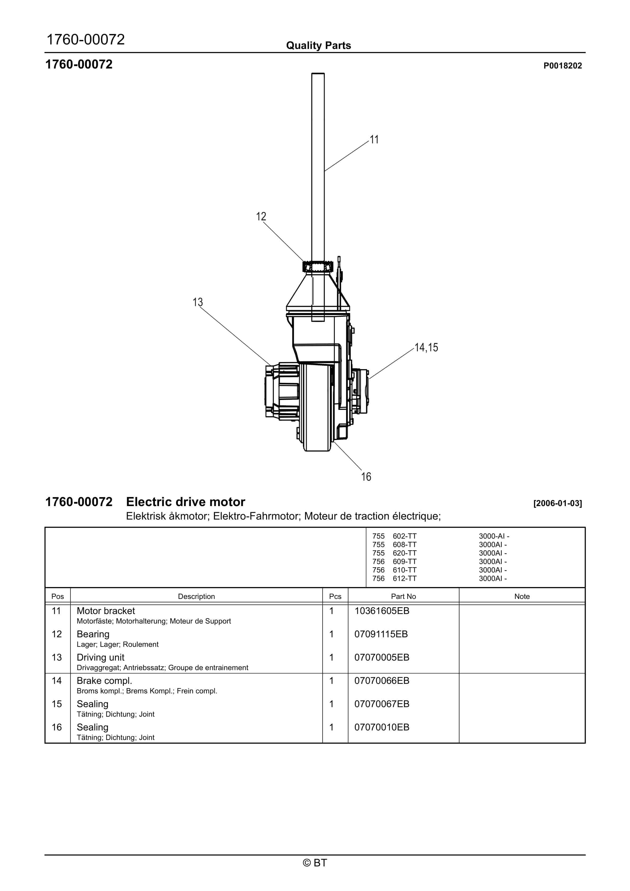
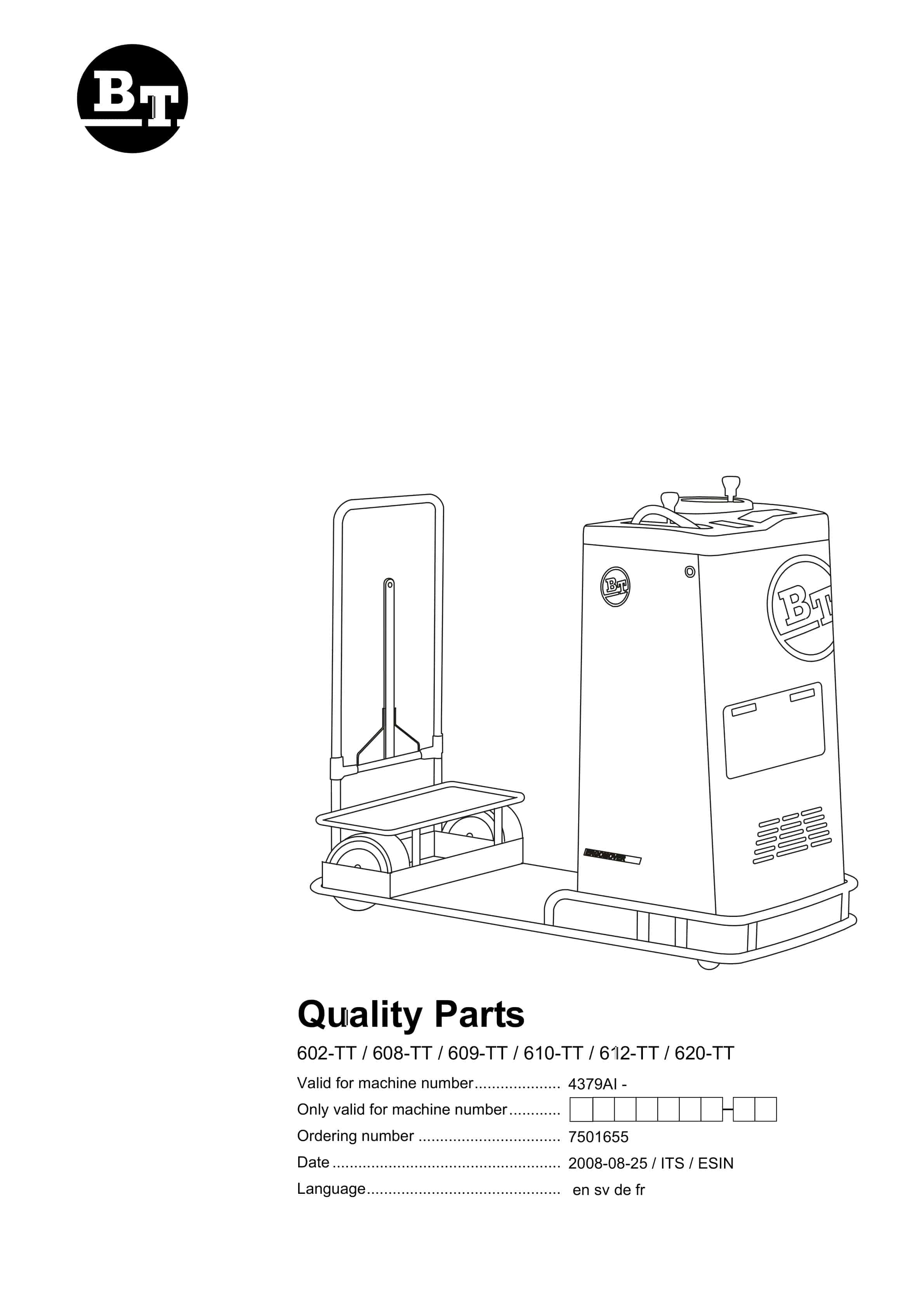
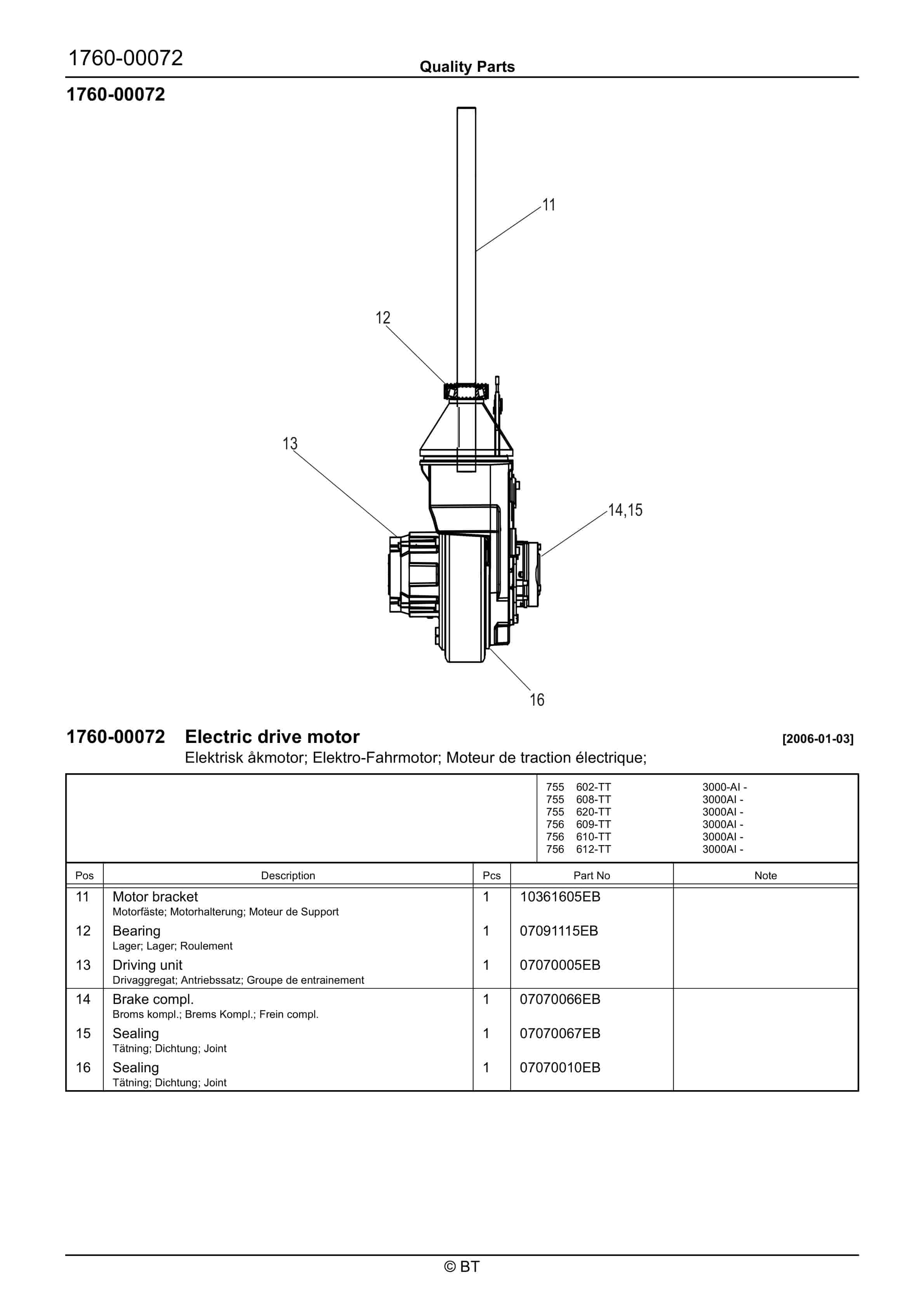
BT 602-TT, 608-TT, 609-TT, 610-TT, 612-TT, 620-TT Quality Parts 241857
BT 602-TT, 608-TT, 609-TT, 610-TT, 612-TT, 620-TT Quality Parts 7504691
BT CARGO E-Series CBE 12F Spare Parts Catalog 0350163R1-0
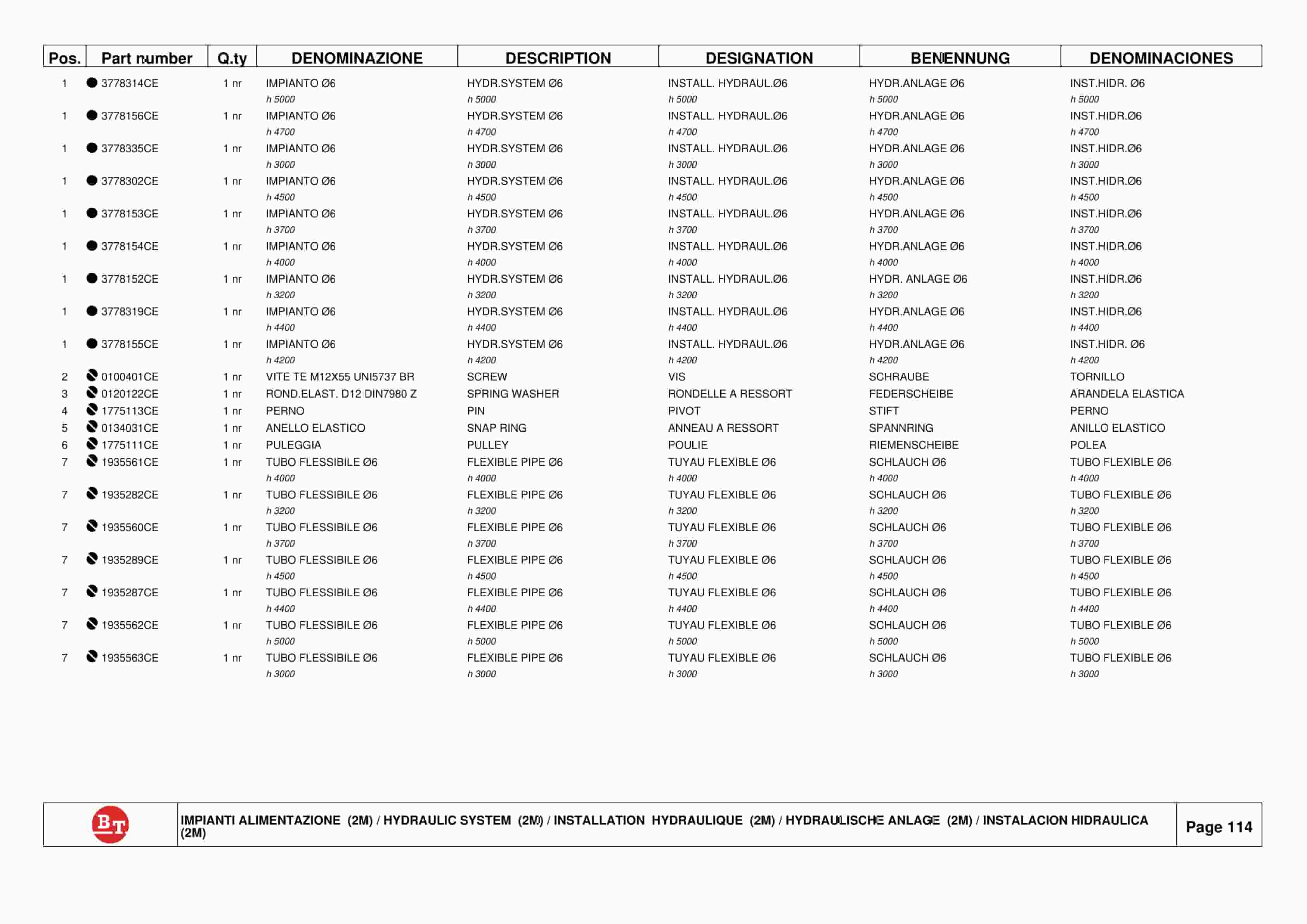
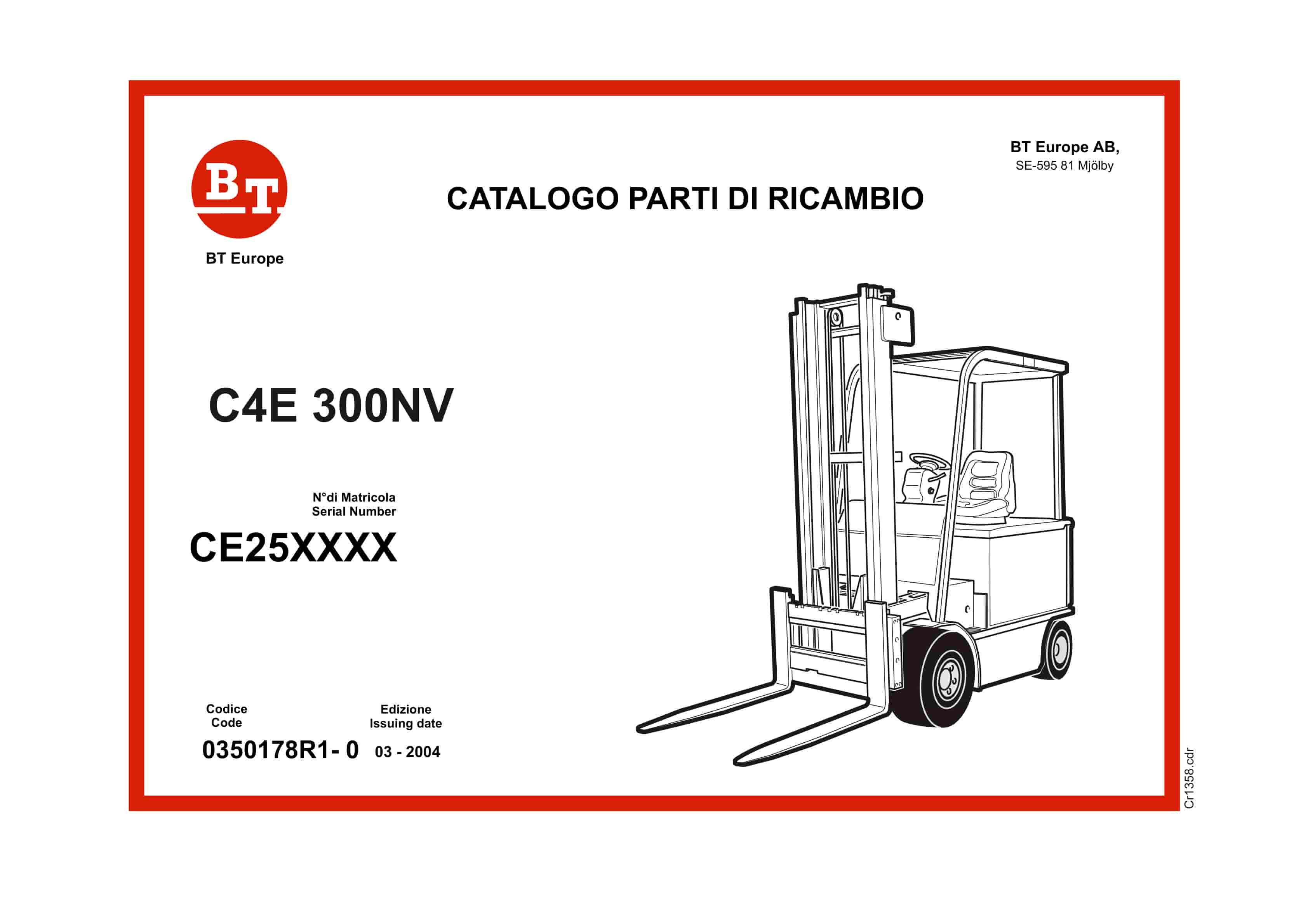
BT C4E 300NV Spare Parts Catalog 0350178R1-0
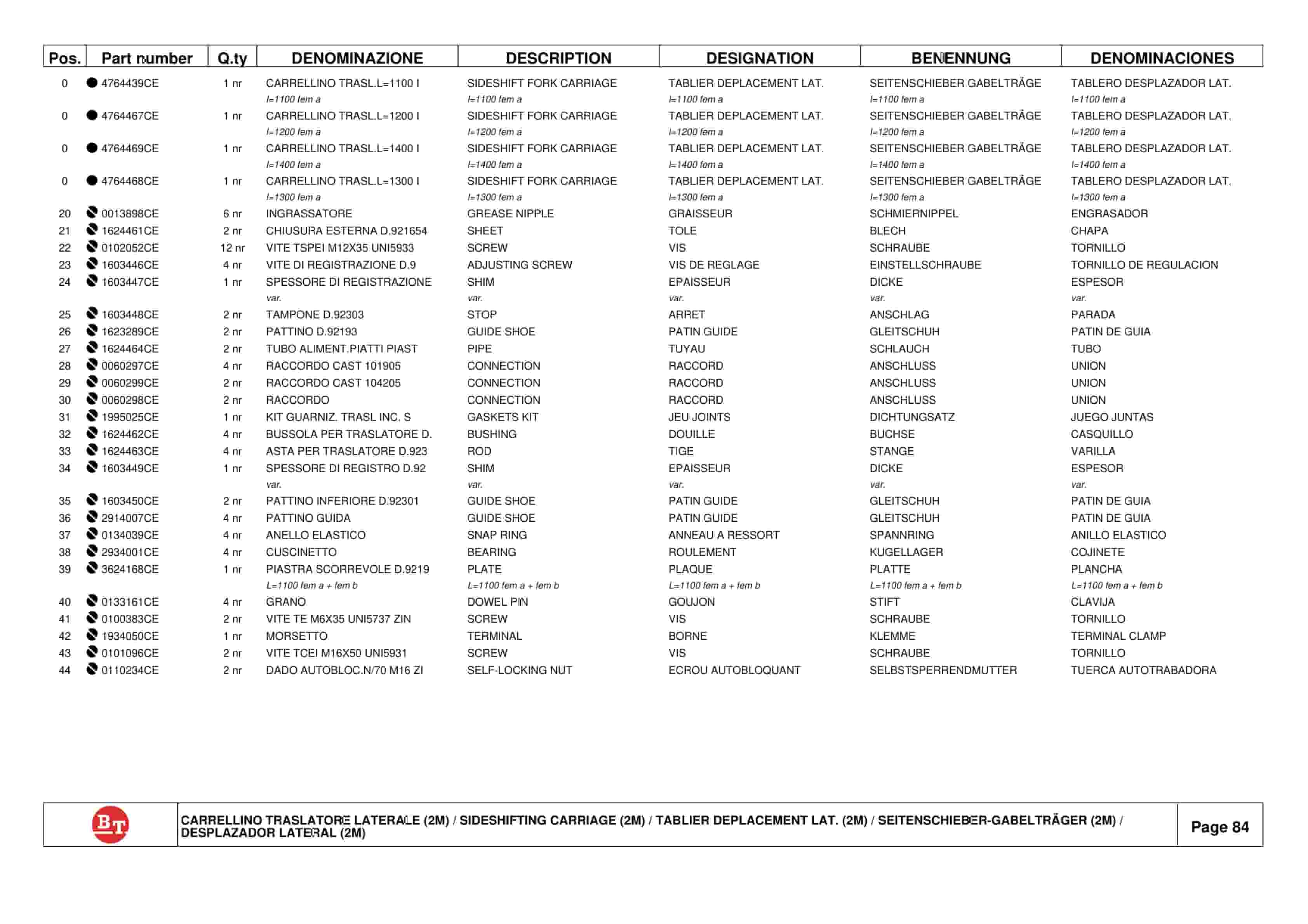
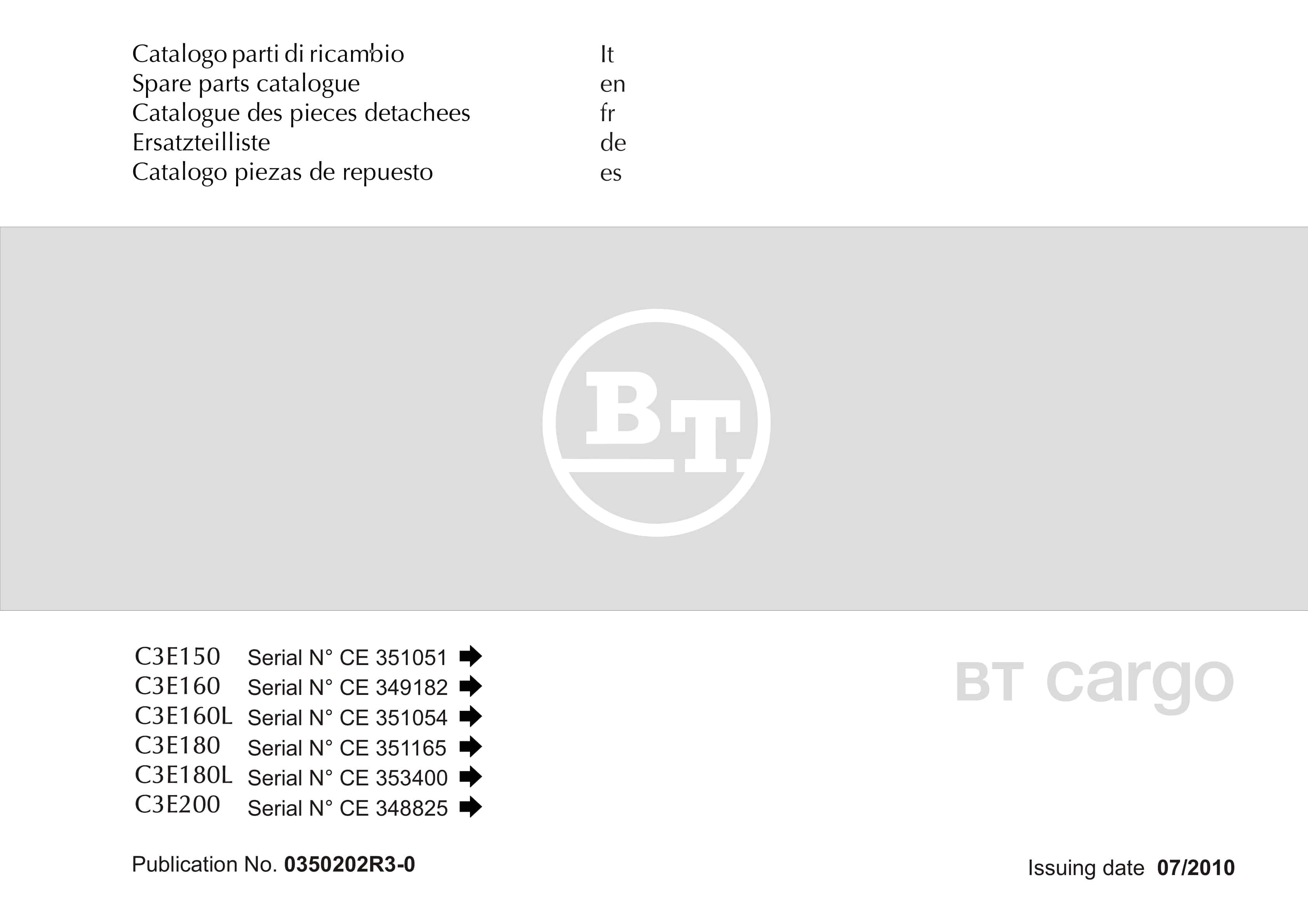
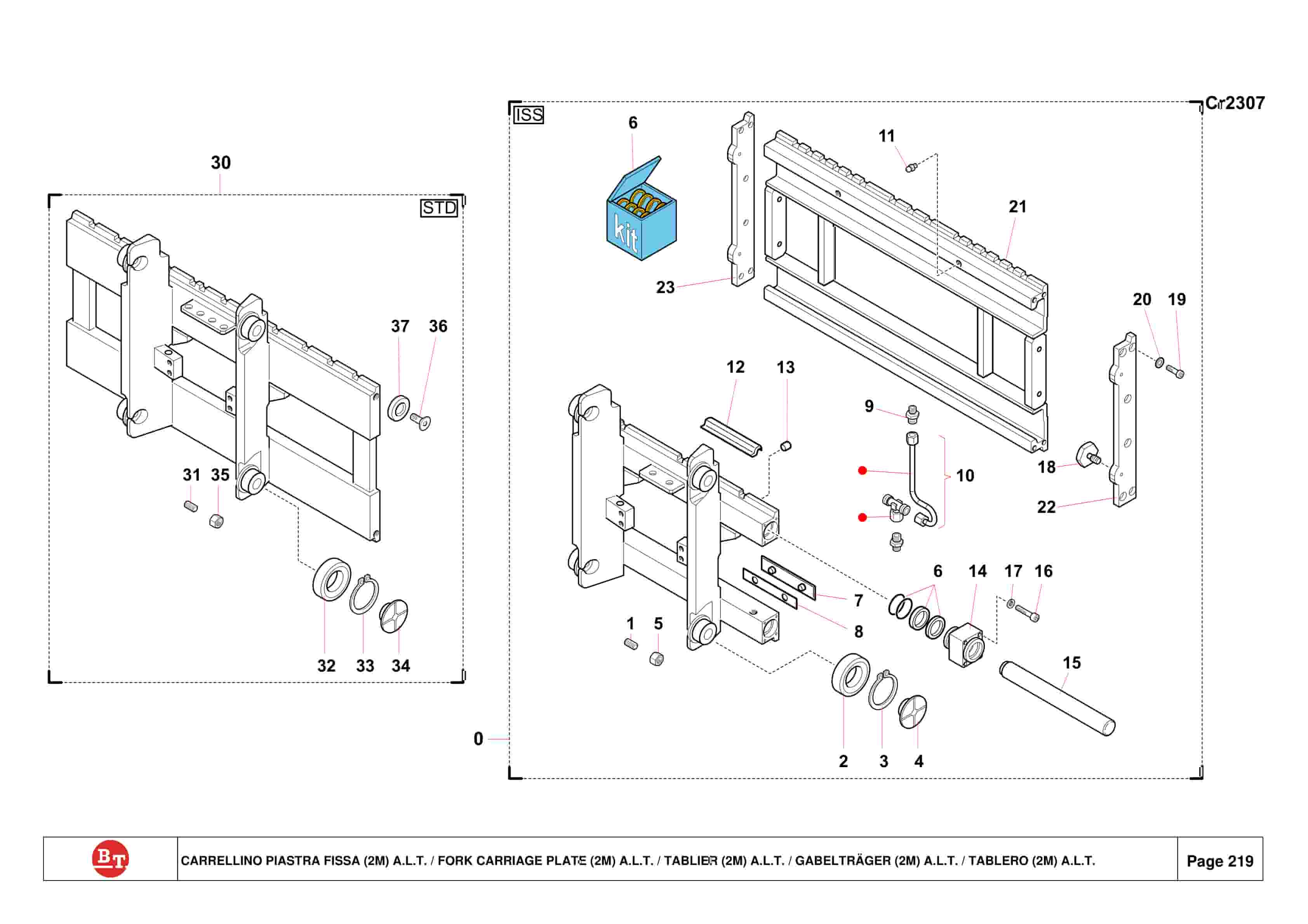
BT C3E150, C3E160, C3E160L, C3E180, C3E180L, C3E200 Spare Parts Catalog 0350202R3-0
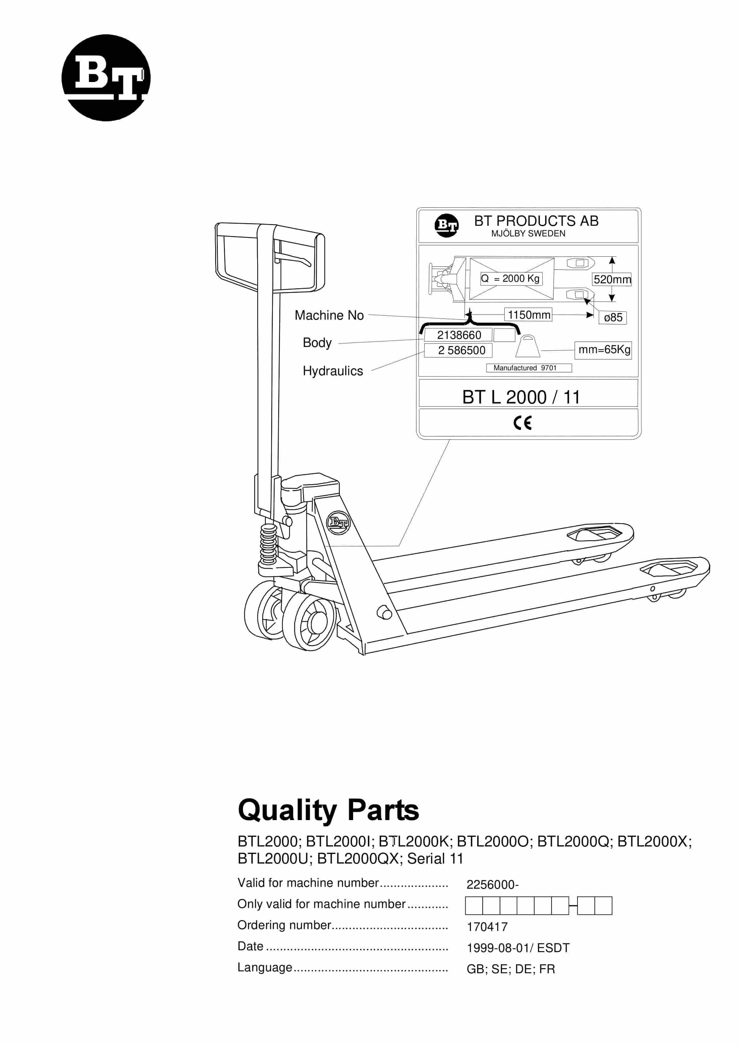
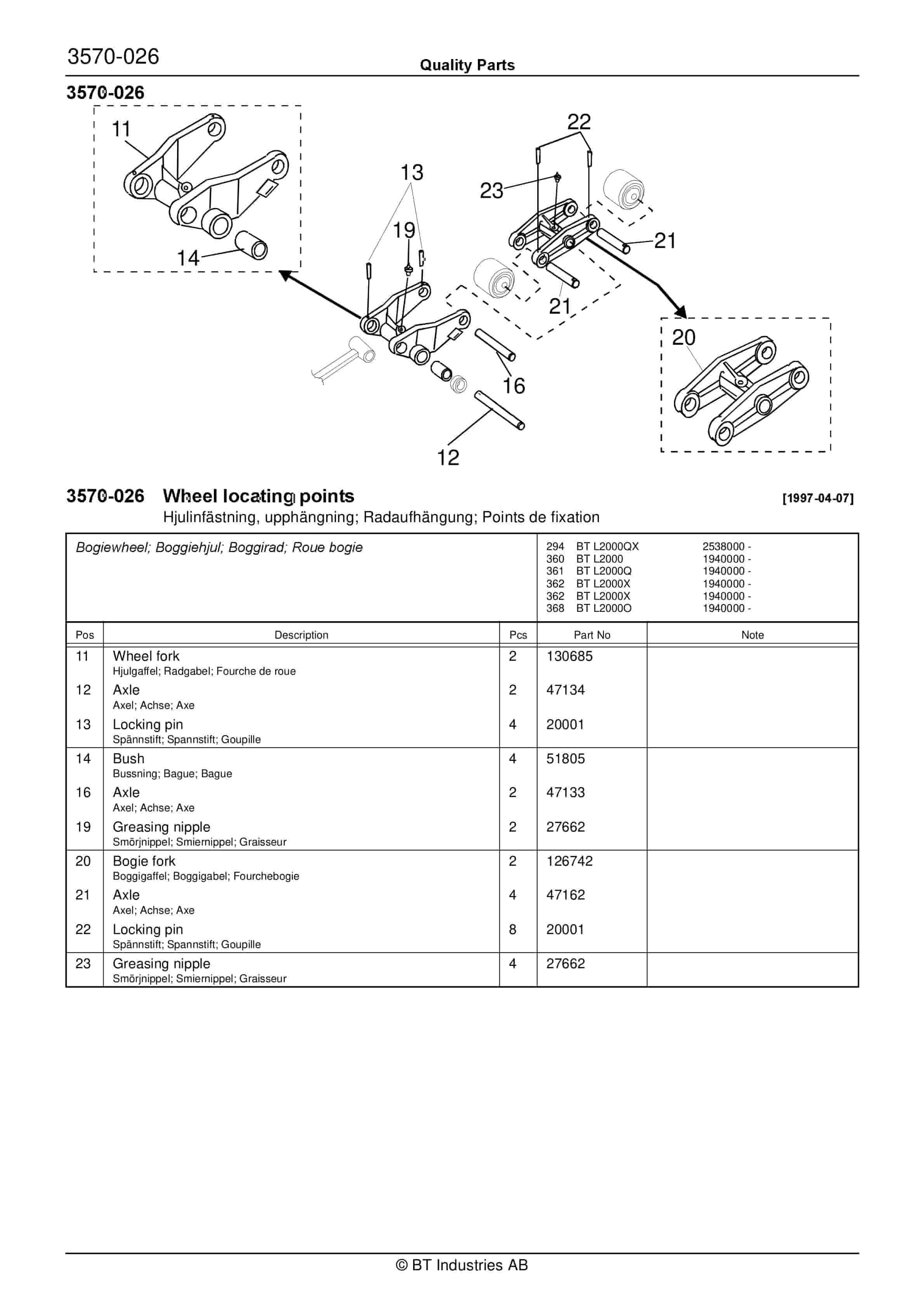
BT BTL2000, BTL2000I, BTL2000K, BTL2000O, BTL2000Q, BTL2000X, BTL2000U, BTL2000QX, Serial 11 Quality Parts 170417
BT 602-TT, 608-TT, 609-TT, 610-TT, 612-TT, 620-TT Quality Parts 7501655
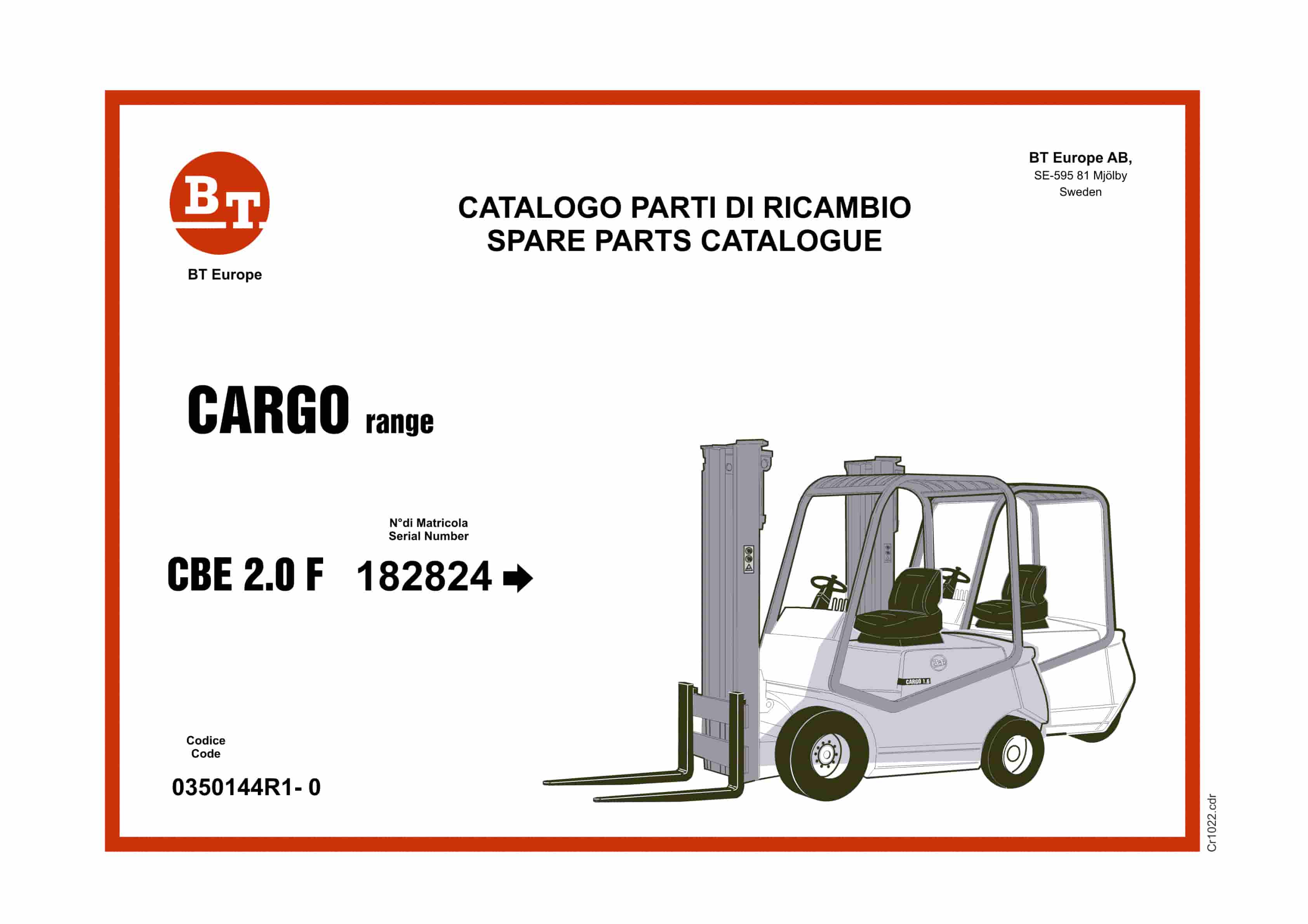
BT CARGO CBE 2.0F Spare Parts Catalog 0350144R1-0


