Description
Table of Content – Multi Pro 5800 (S.N below 316000000)
- Title Page
- Revision History
- Reader Comments
- Preface
- Table Of Contents
- Table Of Contents (Continued)
- 1 – Safety
- Safety Instructions
- Before Operating
- While Operating
- Maintenance and Service
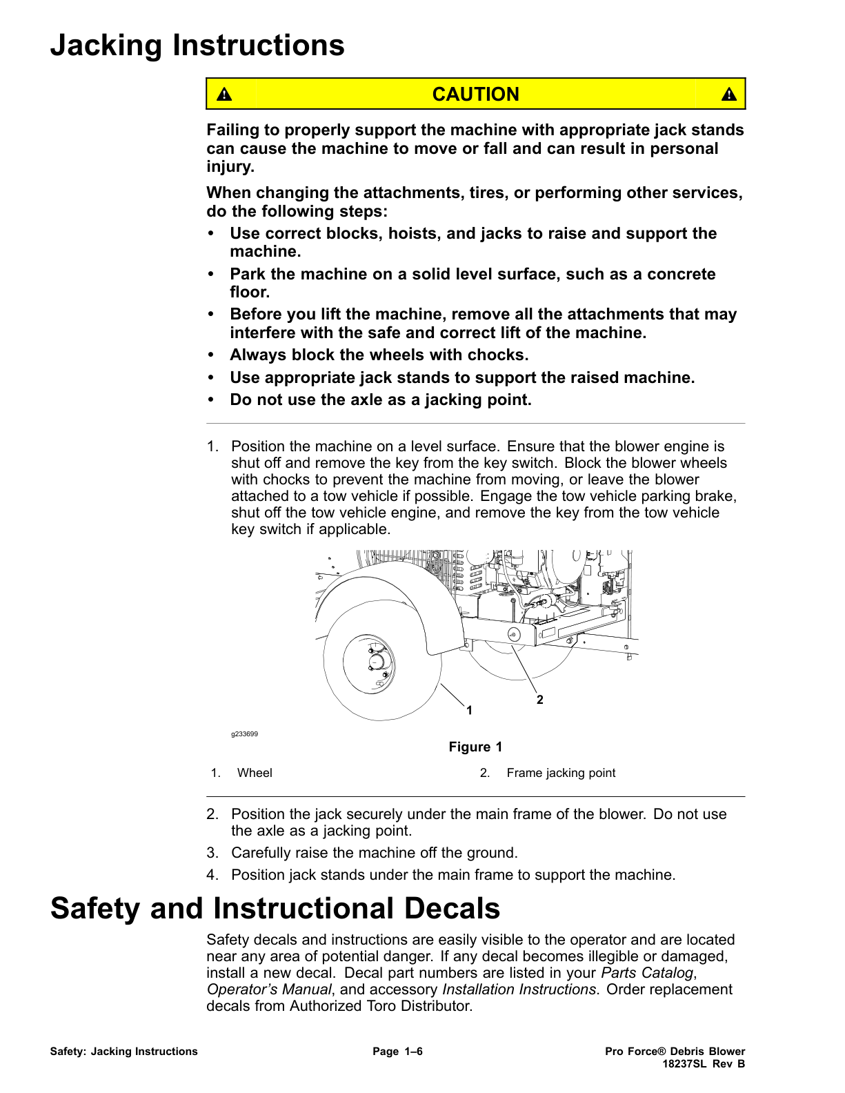
- Jacking Instructions
- Safety and Instruction Decals
- 2 – Product Records and Maintenance
- Product Records
- Maintenance
- Equivalents and Conversions
- Decimal and Millimeter Equivalents
- US to Metric Conversions
- Torque Specifications
- Fastener Identification
- Using a Torque Wrench with an Offset Wrench
- Standard Torque for Dry, Zinc Plated and Steel Fasteners (Inch Series Fasteners)
- Standard Torque for Dry, Zinc Plated and Steel Fasteners (Metric Fasteners)
- Other Torque Specifications
- Conversion Factors
- 3 – Kubota Diesel Engine
- General Information
- Operator’s Manual
- Specifications
- Adjustments
- Adjust Throttle Cable
- Service and Repairs
- Fuel System
- Air Cleaner
- Exhaust System
- Radiator
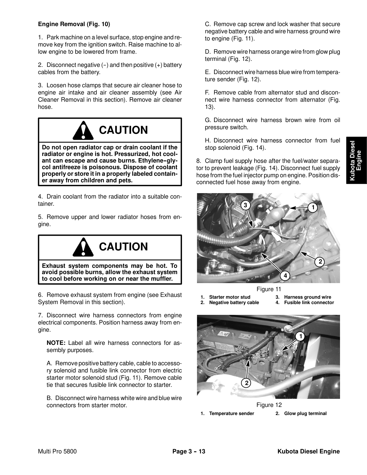
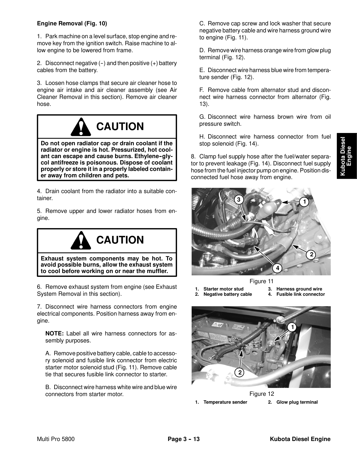
- Engine
- Engine Removal
- Engine Installation
- Flywheel Coupler
- Kubota 05-E3B Series Workshop Manual
- 4 – Hydraulic System
- Specifications
- General Information
- Operator’s Manual
- Check Hydraulic Fluid
- Towing Sprayer
- Traction Circuit Component Failure
- Hydraulic Hoses
- Hydraulic Hose and Tube Installation (O–Ring Face Seal Fitting)
- Hydraulic Fitting Installation (SAE Straight Thread O–Ring Fitting into Component Port)
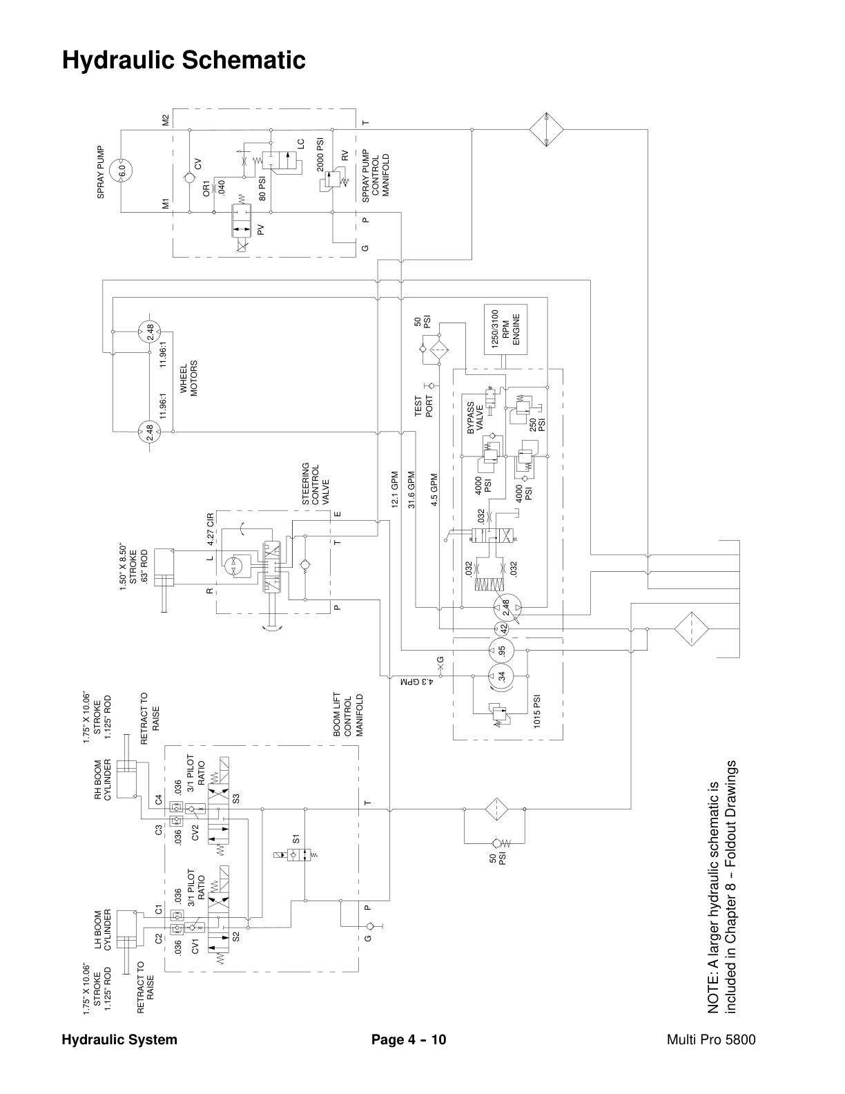
- Hydraulic Schematic
- Hydraulic Flow Circuits
- Traction Circuit
- Steering Circuit
- Spray Pump Drive Circuit
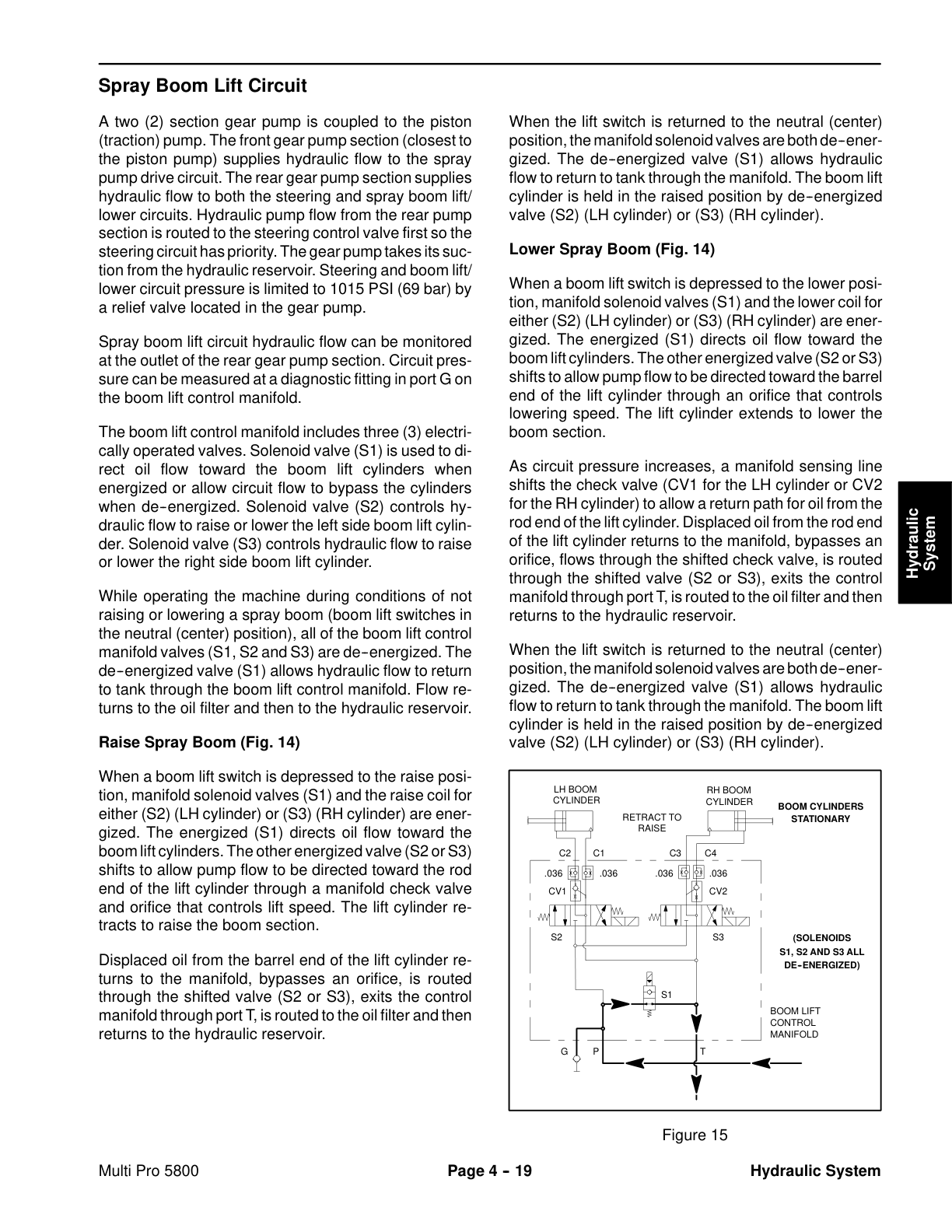
- Spray Boom Lift Circuit
- Special Tools
- Troubleshooting
- Testing
- Traction Circuit Charge Pressure Test
- Traction Circuit Relief Pressure Test
- Wheel Motor Efficiency
- Charge Pump Flow Test
- Piston (Traction) Pump Flow Test
- Steering, Boom Lift Circuits Relief Pressure Test
- Steering, Boom Lift Circuits Gear Pump Flow Test
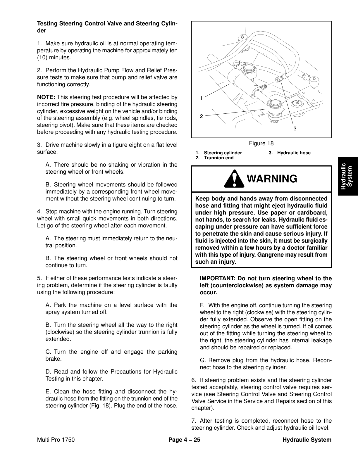
- Steering Cylinder Internal Leakage Test
- Boom Lift Cylinder Internal Leakage Test
- Spray Pump Circuit Gear Pump Flow Test
- Adjustments
- Adjust Traction Pedal for Neutral
- Service and Repairs
- General Precautions for Removing and Installing Hydraulic System Components
- Check Hydraulic Lines and Hoses
- Flush Hydraulic System
- Filtering Closed–Loop Traction Circuit
- Charge Hydraulic System
- Gear Pump
- Gear Pump Service
- Piston (Traction) Pump
- Piston (Traction) Pump Service
- Wheel Motors
- Wheel Motor Service
- Spray Pump Drive Motor
- Spray Pump Drive Motor Service
- Spray Pump Control Manifold
- Spray Pump Control Manifold Service
- Steering Control Valve
- Steering Control Valve Service
- Steering Cylinder
- Steering Cylinder Service
- Boom Lift Control Manifold
- Boom Lift Control Manifold Service
- Boom Lift Cylinder
- Boom Lift Cylinder Service
- Oil Cooler
- Hydraulic Reservoir
- Eaton Piston Pump Repair Information
- Eaton Piston Motor Repair Information
- Parker Torqlink Service Procedure
- Danfoss Steering Unit Service Repair Manual
- 5 – Electrical System
- General Information
- Electrical Drawings
- Operator’s Manual
- Special Tools
- Troubleshooting
- Starting Problems
- General Run Problems
- Electrical System Quick Checks
- Battery Test (Open Circuit Test)
- Charging System Test
- Glow Plug System Test
- Neutral Switch Operation
- Component Testing
- Ignition Switch
- Indicator Lights
- Hour Meter
- Headlight Switch
- Speed Lock Switch
- Pressure Rate Switch
- Boom Lift Switches
- Spray Pump, Agitation and Boom Control Switches
- Master Boom (Foot) Switch
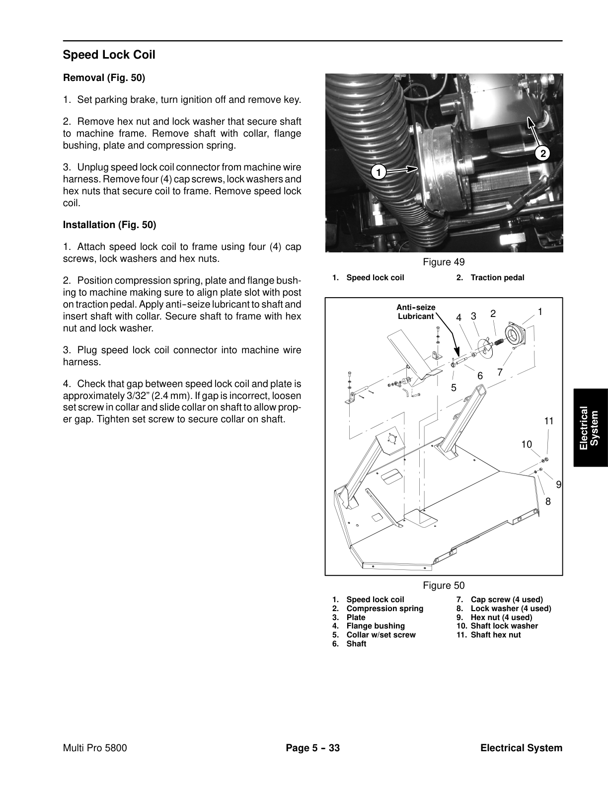
- Speed Lock Coil
- Brake Pedal Switch
- Spray System Relays
- Main, Glow and Speed Lock Relays
- Traction Speed Sensor
- Hydraulic Valve Solenoid Coils
- Manual Interface Module
- Neutral Switch
- Fuel Stop Solenoid
- Glow Plug Controller
- Fuel Pump
- Temperature Sender
- Fusible Links
- Diode Assemblies
- Service and Repairs
- Headlights
- Traction Speed Sensor
- Speed Lock Coil
- Battery Storage
- Battery Care
- Battery Service
- 6 – Spray System
- Specifications
- General Information
- Operator’s Manual
- Precautions Concerning Chemicals Used in Spray System
- Precautions for Removing or Adjusting Spray System Components
- Spray System Flow Diagram
- Spray System Operation
- Troubleshooting
- Service and Repairs
- Spray Pump
- Spray Pump Service
- Agitation Supply
- Pressure Relief Valve
- Spray Control Assembly
- Boom Manifold Valve Assembly
- Agitation Valve Assembly
- Boom and Agitation Valve Motor Service
- Tank Suction
- Tank Drain Valve
- Turret Bodies
- Turret Body Service
- Boom Hinge
- Pro Control XP Spray System (Optional)
- 7 – Chassis
- Table of Contents
- Specifications
- General Information
- Operator’s Manual
- Adjustments
- Planetary Drive Assembly Endplay (OPH-2 series planetary drives)
- Service and Repairs
- Tie Rod Ends
- Front Wheels and Hubs
- Spindles
- Front Suspension
- Brake Assembly
- Brake Inspection and Repair
- Brake Cables
- Planetary Wheel Drive Assembly
- OPH-2 Series Planetary Drive Service
- VA02 Series Planetary Drive Service
- Console Assembly
- 7.1 – Ultra Sonic Boom System(Optional Kit)
- General Information
- Installation Instructions
- Precautions Concerning Chemicals Used in Spray System
- Precautions for Removing or Adjusting Spray System Components
- Special Tools
- Hydraulic Schematic
- Electrical Schematic
- Ultra Sonic Boom System Operation
- Sprayer Operation on Level Turf
- Downward Slope in Turf Encountered
- Rise in Turf Encountered
- Boom Level Changed by Operator
- Manual Boom Operation
- Troubleshooting
- Sonic Boom Light
- Ultra Sonic Boom Calibration
- Diagnostic Lamp
- Diagnostic Display
- Troubleshooting Chart
- Service and Repairs
- Sonic Boom Fuses
- Sonic Boom Switch
- Sonic Sensors
- Toro Electronic Controller (TEC)
- Boom Lift Control Manifold
- 8 – Foldout Drawings
- Hydraulic Schematic
- Vehicle Electrical Schematic
- Spray System Electrical Schematic
- Glow Plug Circuit
- Start Circuit
- Run Circuit
- Speed Lock Circuit
- Front Wire Harness Drawing
- Front Wire Harness Diagram
- Rear Wire Harness Drawing
- Rear Wire Harness Diagram
Rate this product
You may also like
