No products in the cart.
Return to shop
$30.00
Toro
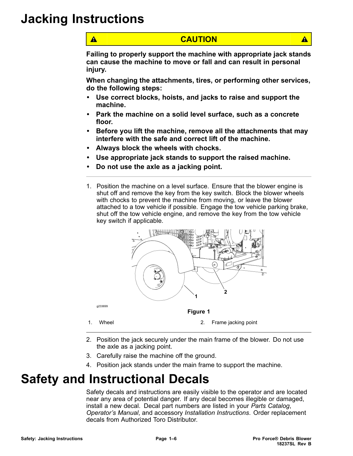
Toro Pro Force Debris Blower (Models 44552, 44552TE, 44553, 44554) Service Repair Manual
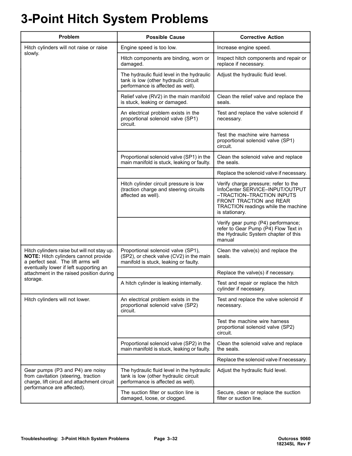
Toro Outcross 9060 Service Repair Manual
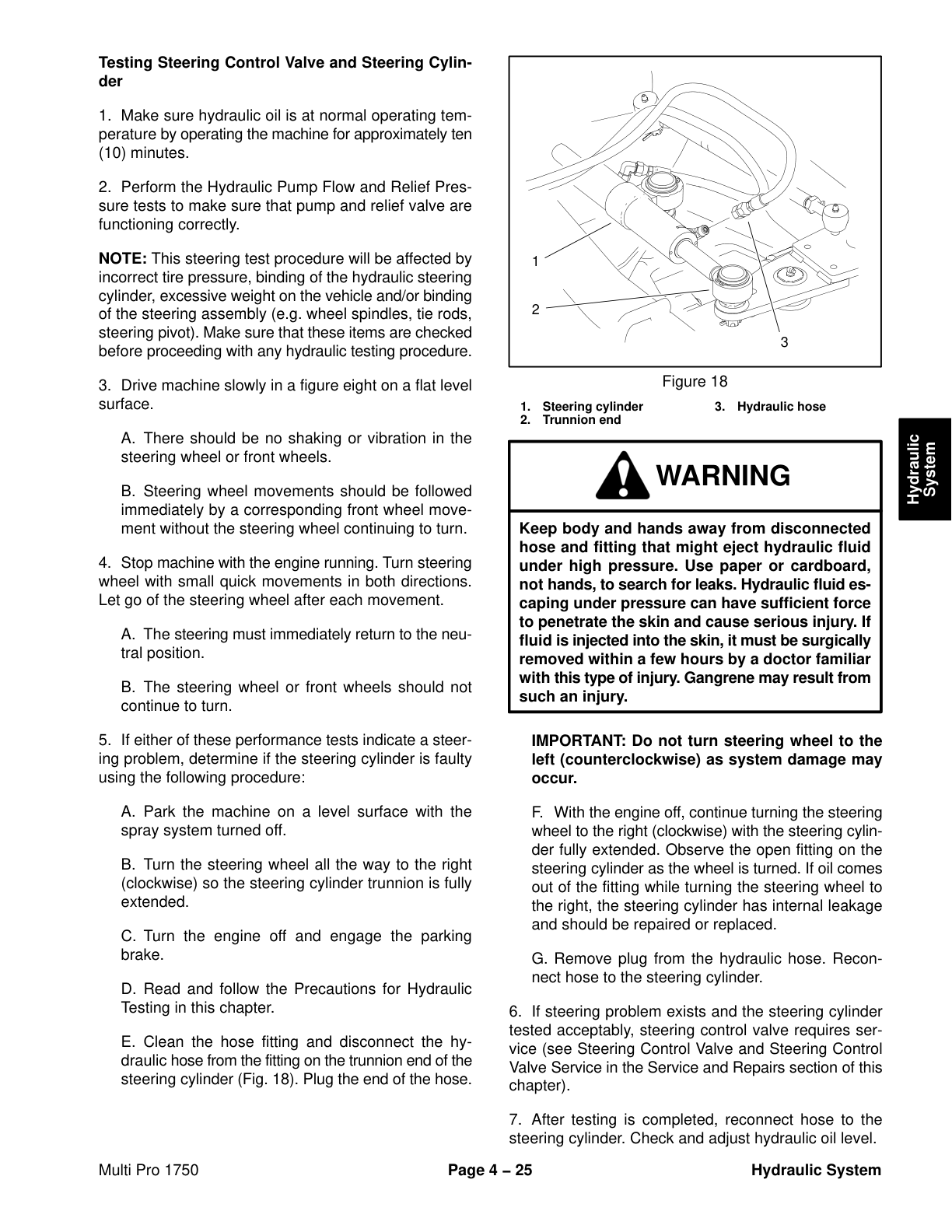
Toro Multi Pro 1750 Service Repair Manual
Toro Groundsmaster 7210 (Tier4) (with Yanmar Engine) Service Repair Manual
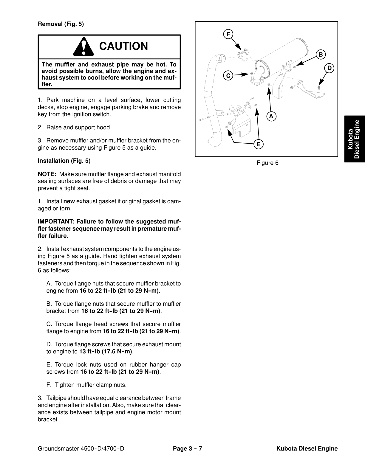
Toro Groundsmaster 4500-D, 4700-D (Model 30857, 30858) Service Repair Manual
Toro Groundsmaster 360 (with Kubota Engine) Service Repair Manual
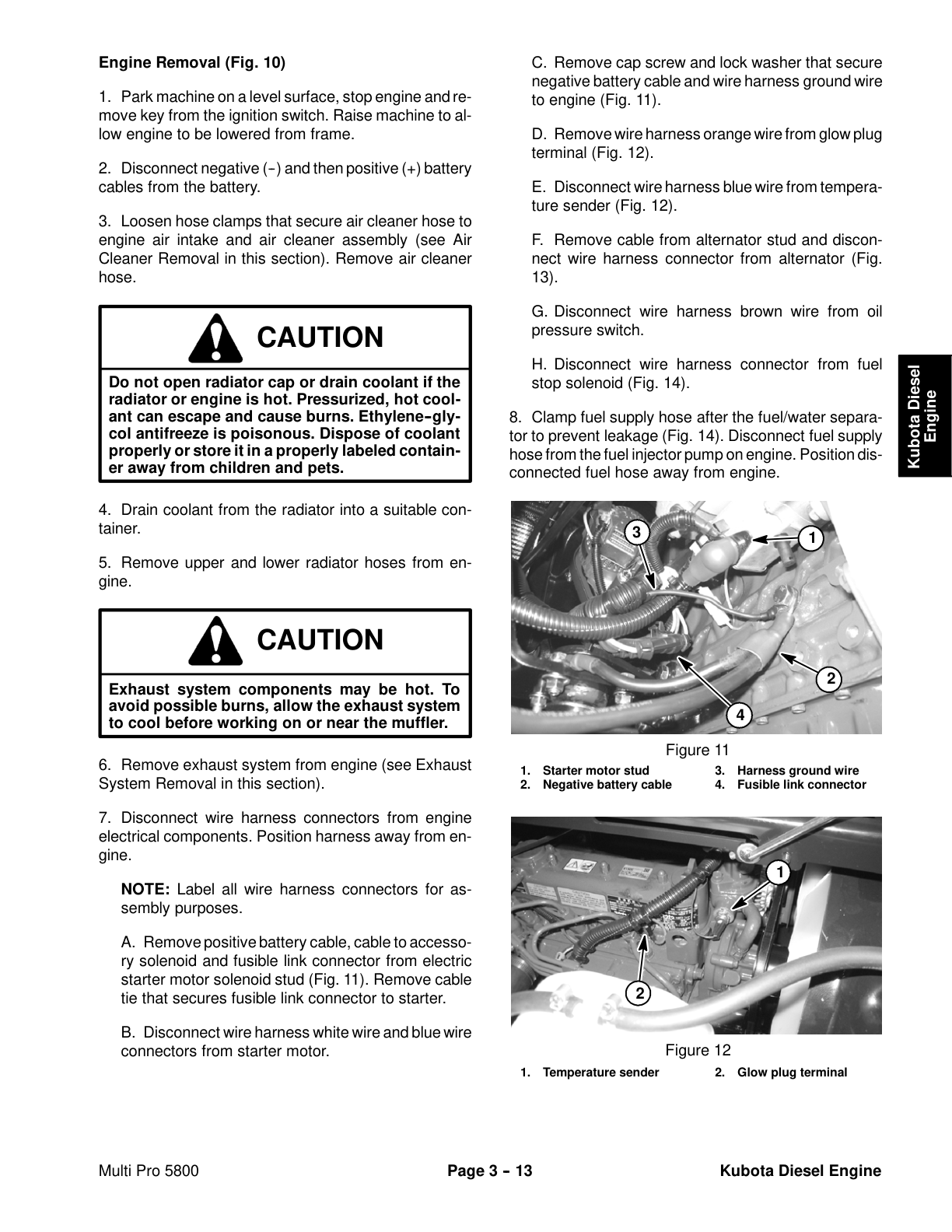
Toro Multi Pro 5800 (S.N below 316000000) Service Repair Manual
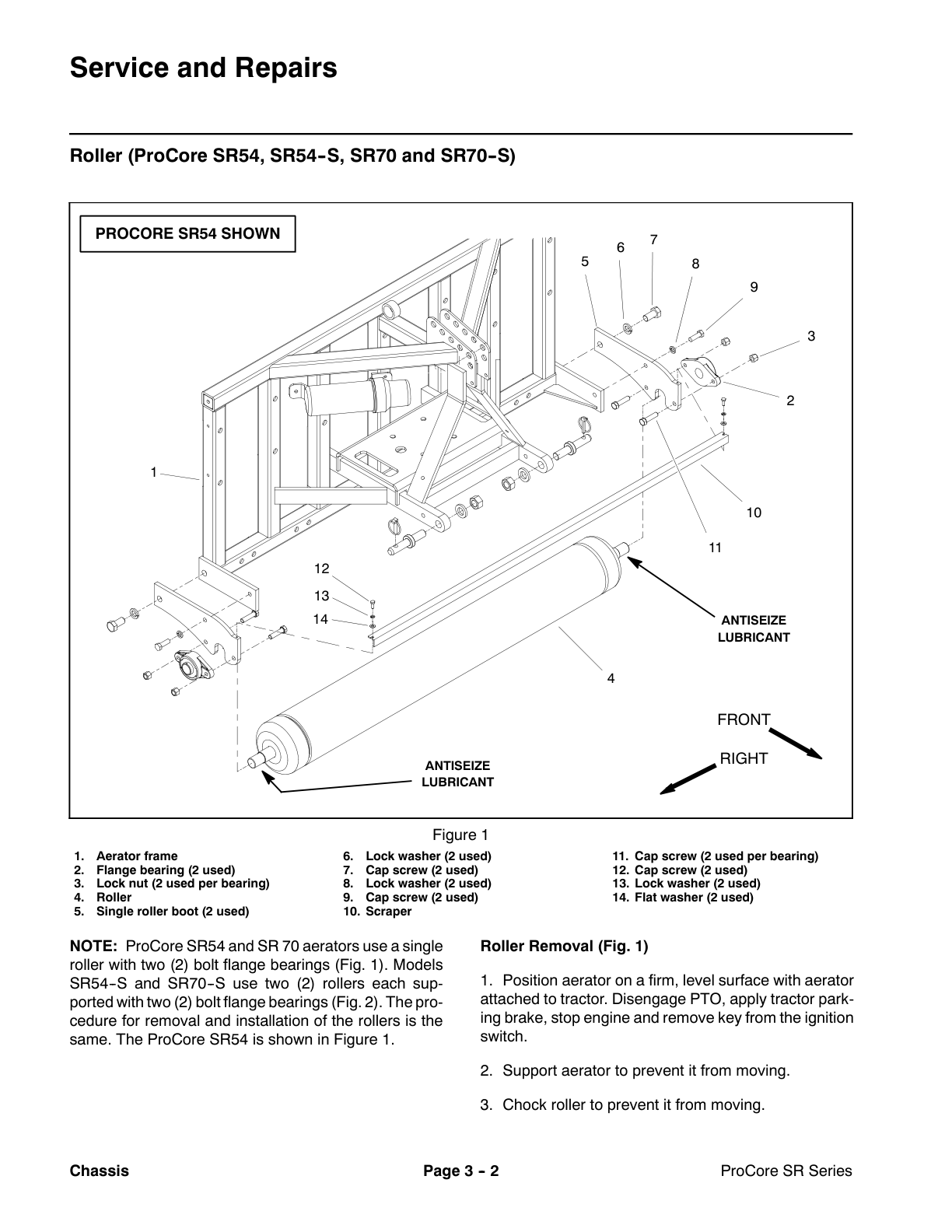
Toro Pro Core SR Deep Tine Aerators Service Repair Manual
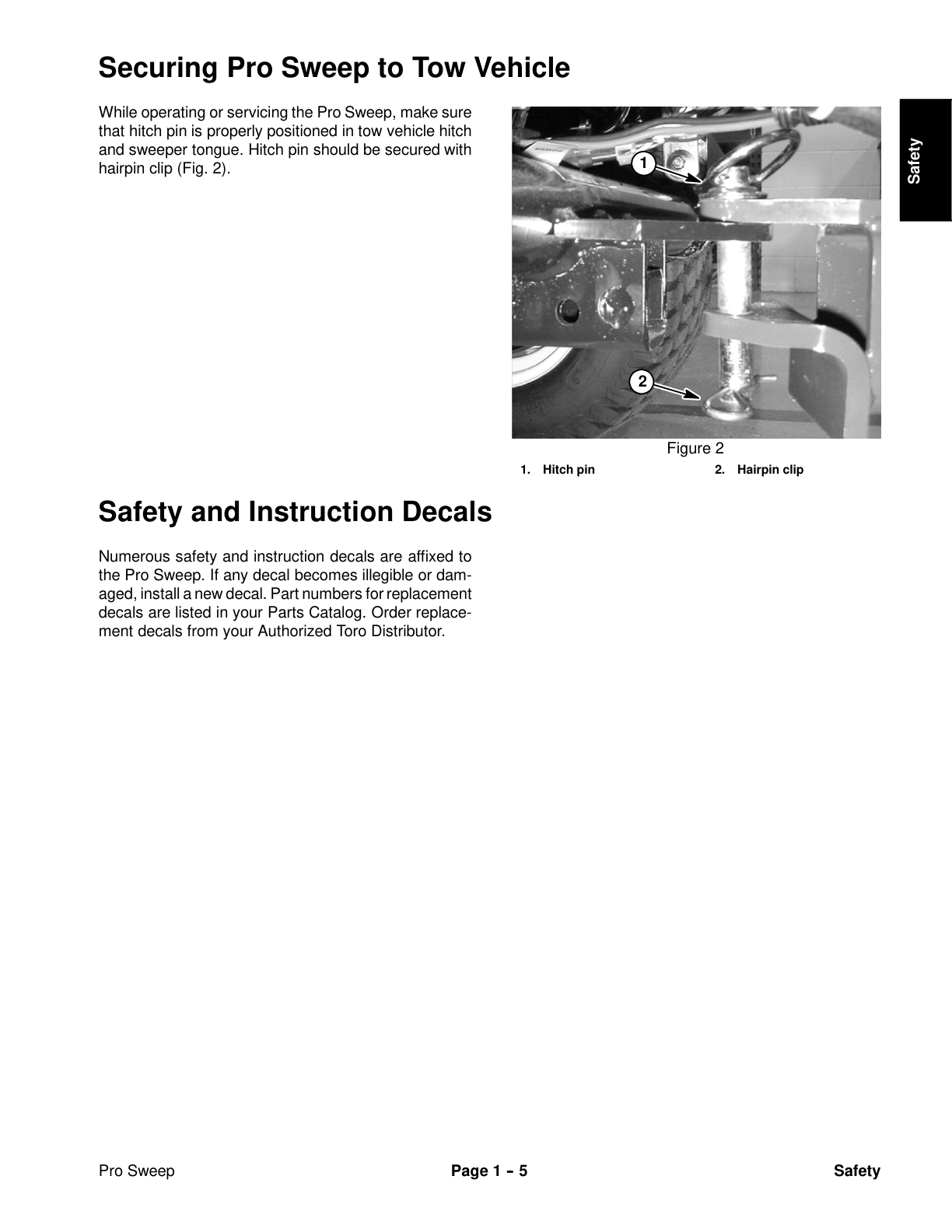
Toro Pro Sweep (Model 07066) Service Repair Manual
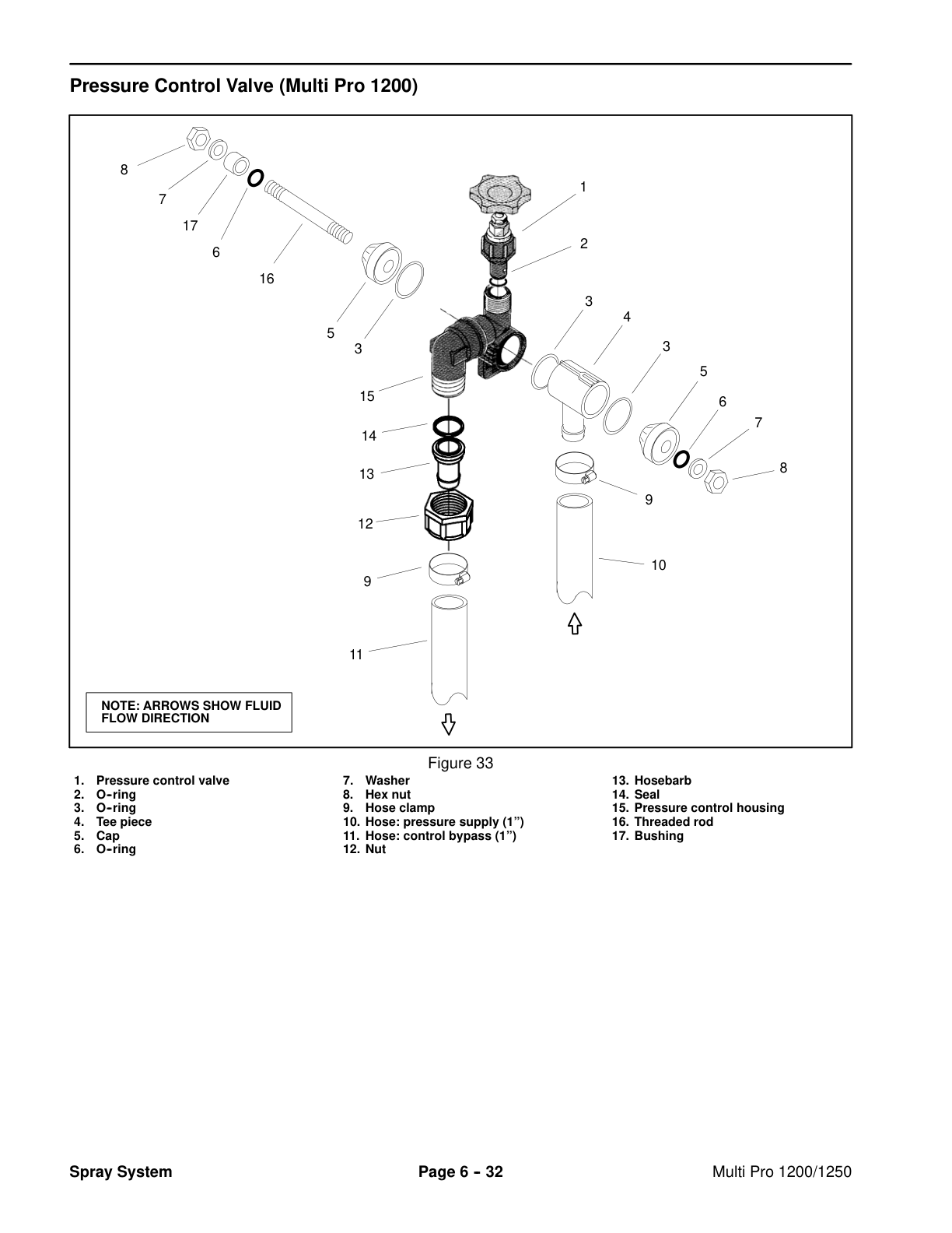
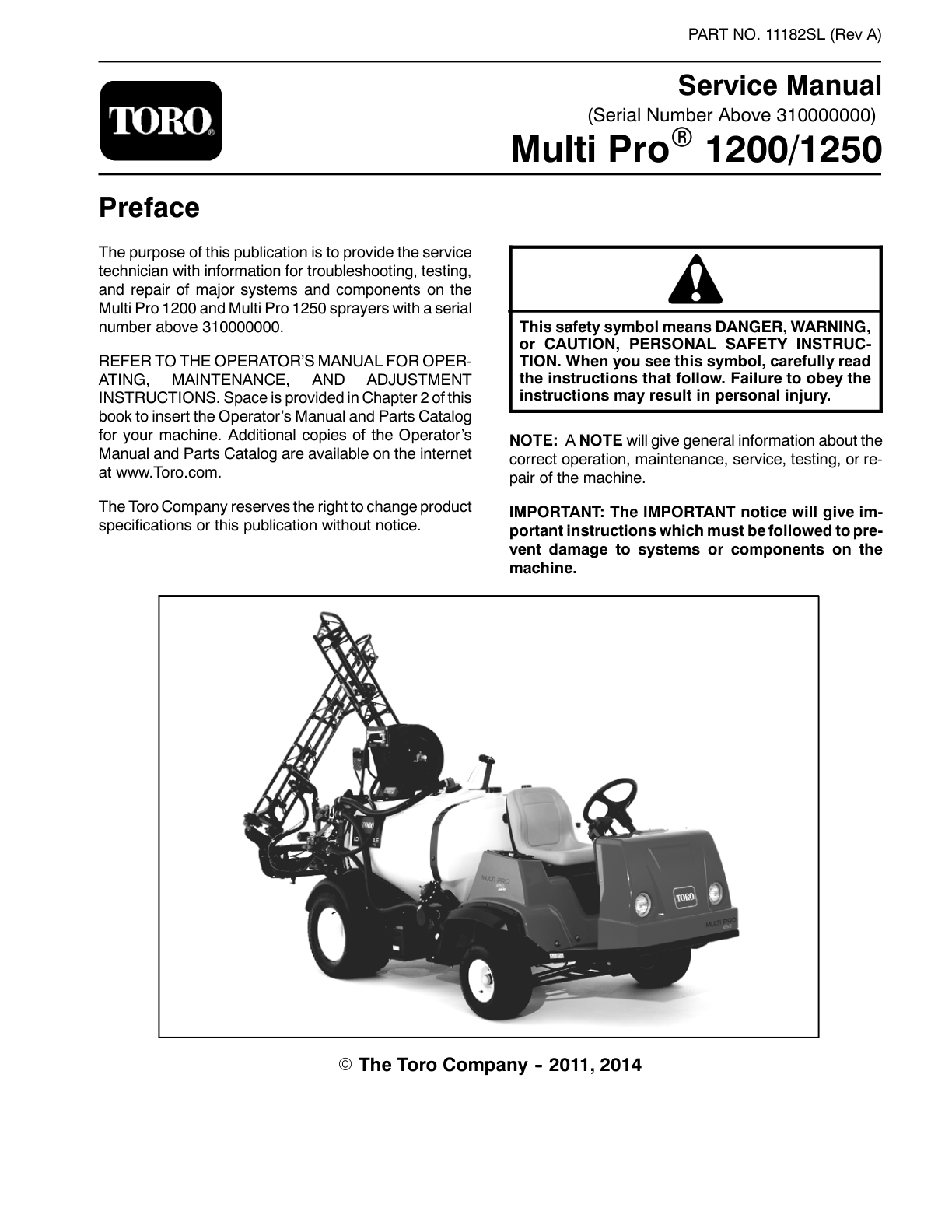
Toro Multi Pro 1200, 1250 (S.N 310000001 & up) Service Repair Manual
 Service Repair Manual 1")
 Service Repair Manual 2")
 Service Repair Manual 3")
 Service Repair Manual 4")
 Service Repair Manual 5")
 Service Repair Manual 6")


%20Service%20Repair%20Manual&url=https://ownersmanualpdf.net/docs/toro-groundsmaster-7200-7210-with-kubota-engine-service-repair-manual/&media=https://ownersmanualpdf.net/wp-content/uploads/2025/09/1-40.png)
%20Service%20Repair%20Manual&url=https://ownersmanualpdf.net/docs/toro-pro-force-debris-blower-models-44552-44552te-44553-44554-service-repair-manual/&media=https://ownersmanualpdf.net/wp-content/uploads/2025/09/pro-force-debris-blower-models-44552-44552te-44553-44554-service-manual_2.png)
%20(with%20Yanmar%20Engine)%20Service%20Repair%20Manual&url=https://ownersmanualpdf.net/docs/toro-groundsmaster-7210-tier4-with-yanmar-engine-service-repair-manual/&media=https://ownersmanualpdf.net/wp-content/uploads/2025/09/1-38.png)
%20Service%20Repair%20Manual&url=https://ownersmanualpdf.net/docs/toro-groundsmaster-4500-d-4700-d-model-30857-30858-service-repair-manual/&media=https://ownersmanualpdf.net/wp-content/uploads/2025/09/groundsmaster-4500-d_4700-d-model-30857-30858-service-manual_2.png)
%20Service%20Repair%20Manual&url=https://ownersmanualpdf.net/docs/toro-groundsmaster-360-with-kubota-engine-service-repair-manual/&media=https://ownersmanualpdf.net/wp-content/uploads/2025/09/1-37.png)
%20Service%20Repair%20Manual&url=https://ownersmanualpdf.net/docs/toro-multi-pro-5800-s-n-below-316000000-service-repair-manual/&media=https://ownersmanualpdf.net/wp-content/uploads/2025/09/11181sl_p33.png)
%20Service%20Repair%20Manual&url=https://ownersmanualpdf.net/docs/toro-pro-sweep-model-07066-service-repair-manual/&media=https://ownersmanualpdf.net/wp-content/uploads/2025/09/10179sl_p13.png)
%20Service%20Repair%20Manual&url=https://ownersmanualpdf.net/docs/toro-multi-pro-1200-1250-s-n-310000001-up-service-repair-manual/&media=https://ownersmanualpdf.net/wp-content/uploads/2025/09/11182sl_p132.png)