Description
Table of Content – Pro Core 648 Aerator
- Title Page
- Revision History
- Reader Comments
- Preface
- Table Of Contents
- 1 – Safety
- Safety Instructions
- Before Operating
- While Operating
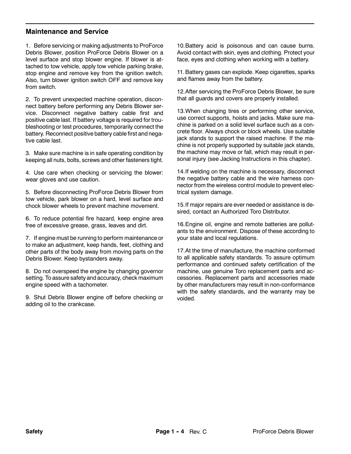
- Maintenance and Service
- Jacking Instructions
- Safety and Instruction Decals
- 2 – Product Records and Maintenance
- Product Records
- Maintenance
- Equivalents and Conversions
- Decimal and Millimeter Equivalents
- U.S. to Metric Conversions
- Torque Specifications
- Fastener Identification
- Standard Torque for Dry, Zinc Plated and Steel Fasteners (Inch Series)
- Standard Torque for Dry, Zinc Plated and Steel Fasteners (Metric Fasteners)
- Other Torque Specifications
- Conversion Factors
- 3 – Kohler Engine
- Introduction
- Specifications
- General Information
- Fuel Shutoff Valve
- Adjustments
- Adjust Choke Control
- Adjust Engine Speed
- Service and Repairs
- Cooling System
- Fuel System
- Fuel Evaporative Control System
- Exhaust System
- Engine
- Belt Tensioners
- Kohler Engine Service Repair Manual
- 4 – Hydraulic System
- Specifications
- General Information
- Hydraulic Hoses
- Hydraulic Fitting Installation
- Pushing, Pulling Machine
- Check Hydraulic Fluid
- Relieving Hydraulic System Pressure
- Hydraulic Schematic
- Hydraulic Flow Diagrams
- Traction Circuit (Forward Shown)
- Coring Head Raise, Lower Circuits
- Special Tools
- Hydraulic Pressure Test Kit
- Hydraulic Tester (Pressure and Flow)
- Hydraulic Test Fitting Kit
- Wheel Hub Puller
- Troubleshooting
- Testing
- Charge Pressure Test (Using Pressure Gauge)
- Coring Head Raise, Lower Relief (R1) Pressure Test (Using Pressure Gauge)
- Traction (Piston) Pump (P1) Flow Test (Using Tester With Flow Meter and Pressure Gauge)
- Traction Circuit Relief Pressure Test (Using Tester With Flow Meter and Pressure Gauge)
- Gear Pump (P2) Flow Test (Using Tester With Flow Meter and Pressure Gauge)
- Wheel Motor Efficiency Test (Using Tester With Flow Meter and Pressure Gauge)
- Service and Repairs
- General Precautions for Removing and Installing Hydraulic System Components
- Check Hydraulic Lines and Hoses
- Flush Hydraulic System
- Hydraulic System Start–up
- Hydraulic Pump Drive Belt
- Hydraulic Pump Control Assembly
- Hydraulic (Traction, Charge) Pump
- Hydraulic (Traction, Charge) Pump Service
- Wheel Motors
- Wheel Motor Service
- Hydraulic Lift Control Manifold
- Hydraulic Lift Control Manifold Service
- Lift Cylinder
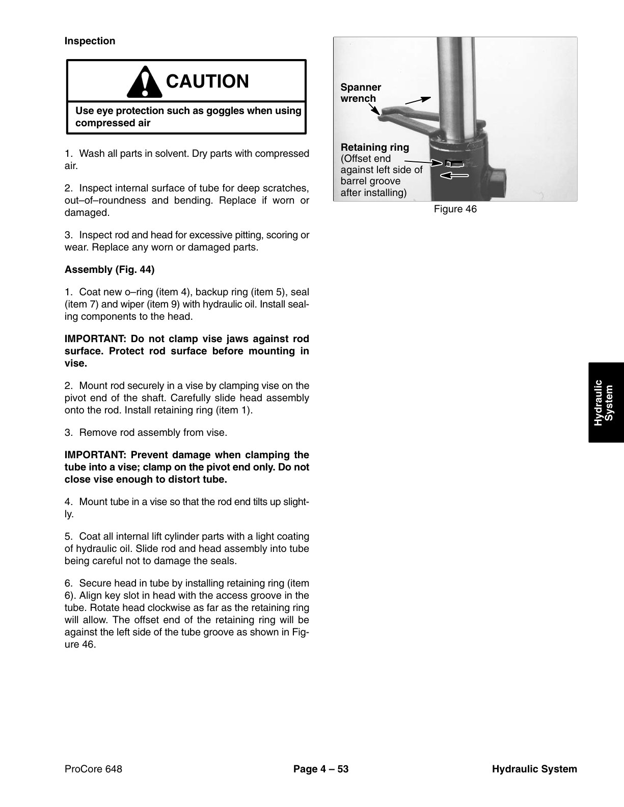
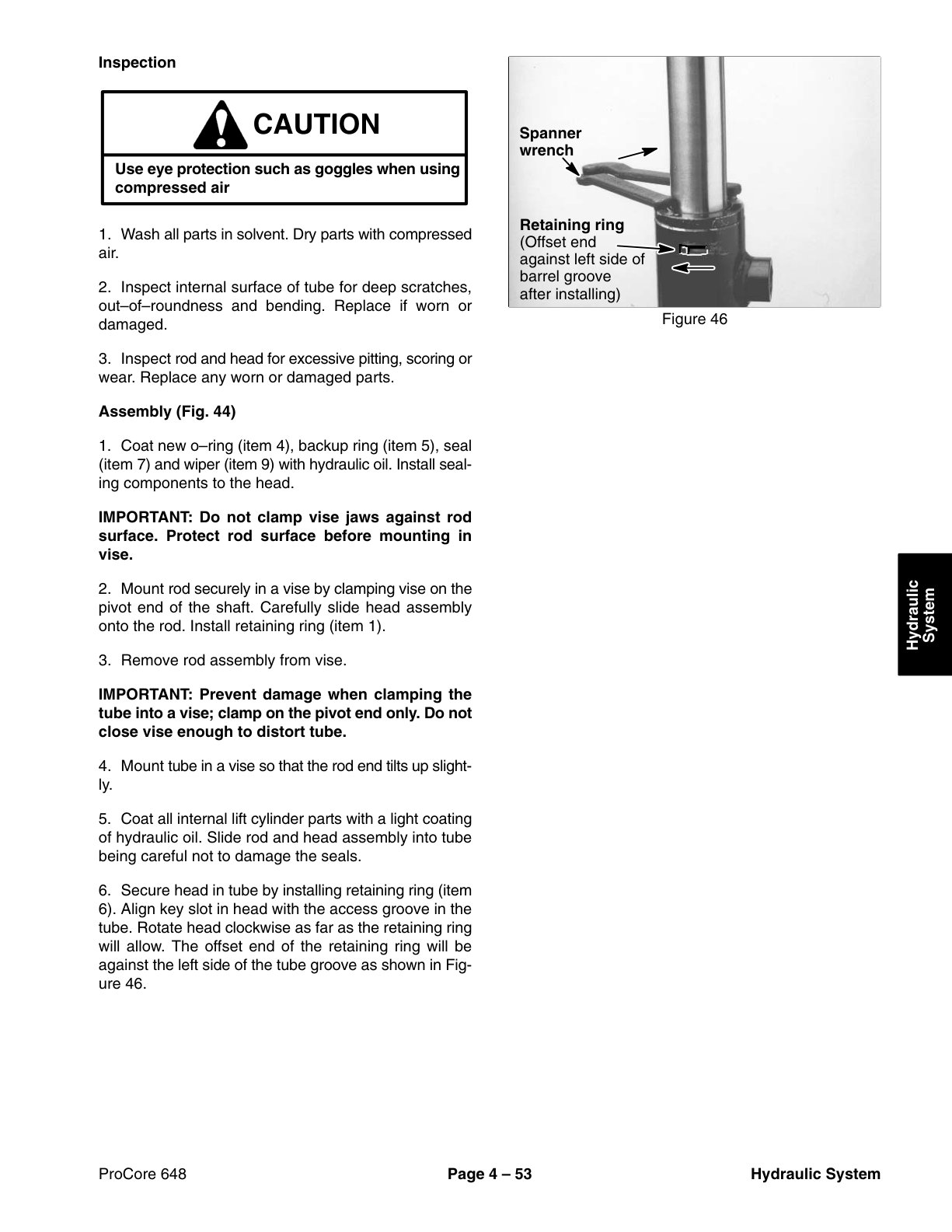
- Lift Cylinder Service
- Hydraulic Reservoir
- Hydro-Gear Hydrostatic Pumps Service and Repair Manual
- Danfoss Gear Pumps and Motors Service Repair Manual
- Danfoss OMEW Hydraulic Motor Service Repair Manual
- 5 – Electrical System
- Electrical Diagrams
- Circuit Operation
- OK to Lower Circuit
- Lockout Circuit
- Electric Clutch Circuit
- Special Tools
- Multimeter
- Battery Terminal Protector
- Battery Hydrometer
- Troubleshooting
- Starting Problems
- General Run Problems
- Coring Head Operating Problems
- Electrical System Quick Checks
- Battery Test (Open Circuit Test)
- Charging System Test
- Check Operation of Safety Interlock System
- Component Testing
- Ignition Switch
- Engine Oil Pressure Indicator Light
- Hour Meter
- Relays
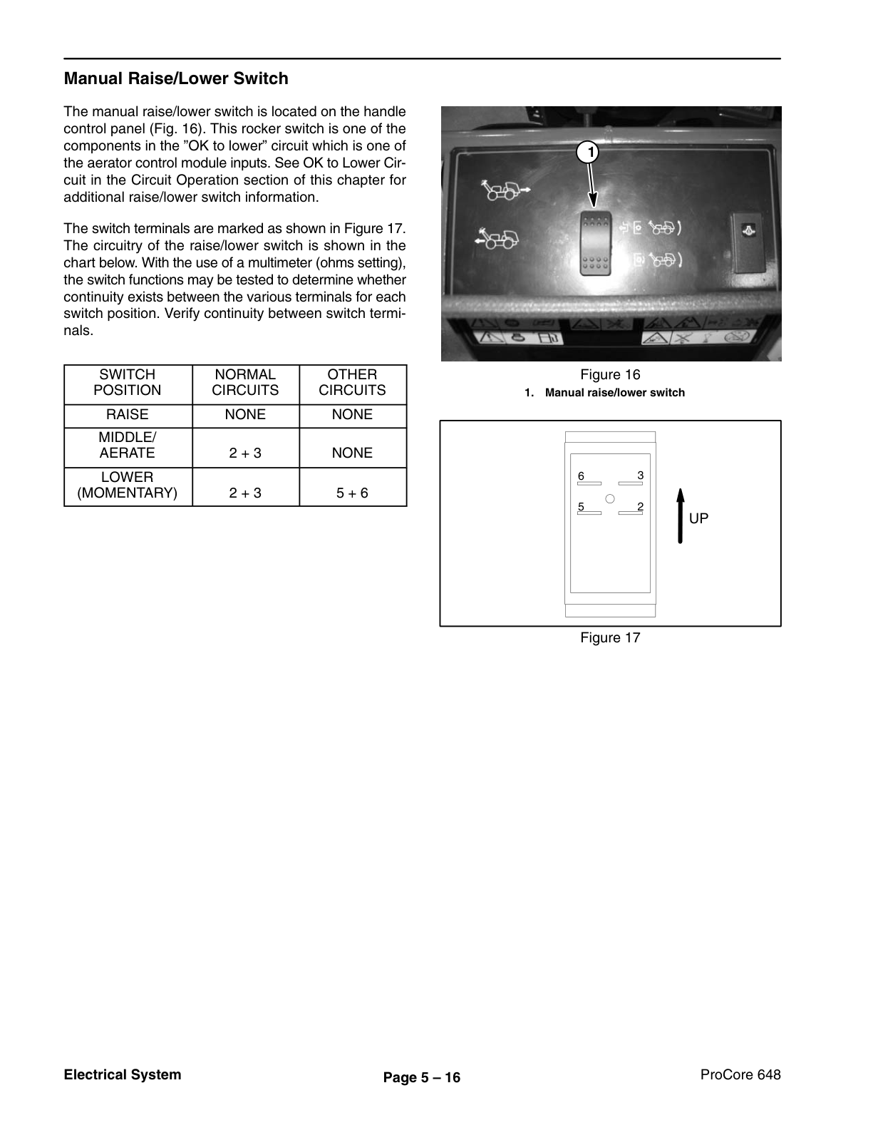
- Manual Raise, Lower Switch
- Ground Follow Switch
- Lift Reset Switch
- Solenoid Valve Coil
- Head Low and Head High Limit Switches
- Fuses
- Proximity Switches
- Aerator Control Module
- Electric Clutch
- Diode Assemblies
- Service and Repairs
- Battery Storage
- Battery Care
- Battery Service
- Electric Clutch
- Solenoid Valve Coil
- 6 – Chassis
- Specifications
- Special Tools
- Wheel Hub Puller
- Service and Repairs
- Wheels
- Parking Brake
- Parking Brake Cable
- Steering Assembly
- Traction Control Cable
- 7 – Coring Head
- General Information
- Coring Head Operation
- Coring Crankshaft
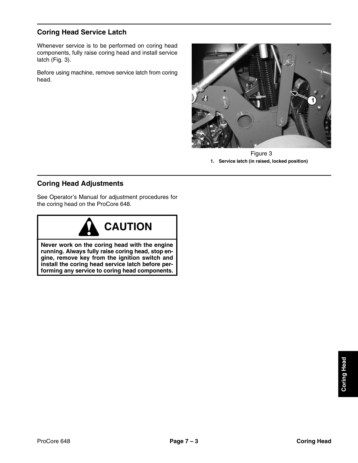
- Coring Head Service Latch
- Coring Head Adjustments
- Service and Repairs
- Rotolink Dampers
- Stomper Arms
- Coring Crankshaft Bearing Housings
- Primary Drive Belt
- Secondary Drive Belt
- Coring Head Drive Jackshaft
- Coring Head Pivot (H–Frame)
- 8 – Electrical Diagrams
- Electrical Schematic (Serial Number Below 403415001)
- Electrical Schematic (Serial Numbers Above 403415001)
- Start Engine
- Lower Coring Head
- Aerating
- Aerating
- Aerating
- Raise Coring Head
- Transport
- Wire Harness Drawing (Serial Number Below 403415001)
- Wire Harness Diagram (Serial Number Below 403415001)
- Wire Harness Drawing (Serial Numbers Above 403415001)
- Wire Harness Drawing (Serial Numbers Above 403415001)
- Untitled
Rate this product
You may also like
