


BT Service Manual PDF
$30.00
BT Service Manual PDF
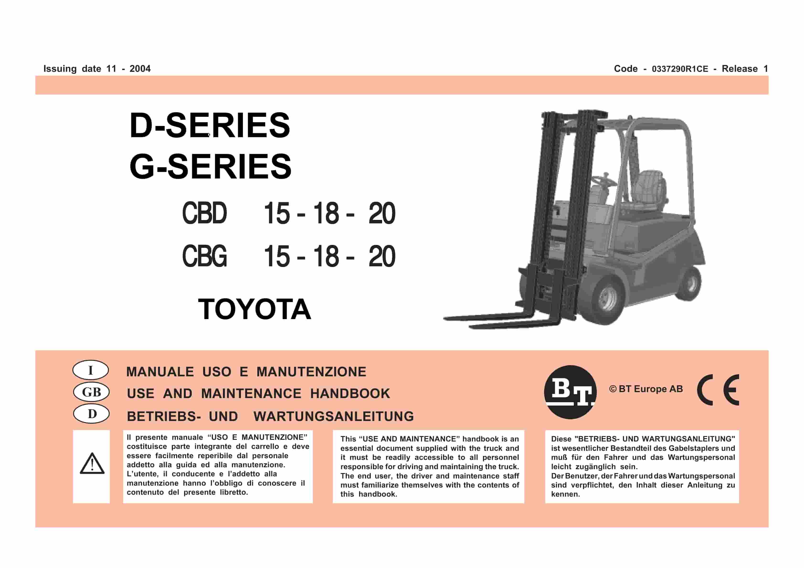
BT D-G-Series CBD15, CBD18, CBD20, CBG15, CBG18, CBG20 Use And Maintenance Handbook 0337290R1CE
$30.00
BT Service Manual PDF
BT Service Manual PDF
BT D-G-Series CBD15, CBD18, CBD20, CBG15, CBG18, CBG20 Use And Maintenance Handbook 0337290R1CE
