BT LPE200 Operator Manual 230509-040
$20.00
- Type Of Manual: Operator Manual
- Manual ID: 230509-040
- : Operator Manual PDF
- Number of Pages: 70
- Size: 5.7MB
- Format: PDF
Category: BT Operator Manual PDF
-
Model List:
- LPE200
- 1. Return To HomePage
- 1.1. Valid from serial number 936513-
- 1.2. Order number 230509-040
- 1.2.1. Issued 2006-02-28 ITS
- 1.2.1.1. It is important that you read this Operators Manual for your own safety
- 2. Safety regulations
- 2.1. Warning symbols
- 2.1.1. Warning levels
- 2.1.1.1. DANGER
- 2.1.1.2. WARNING
- 2.1.1.3. CAUTION
- 2.1.2. Prohibitory symbols
- 2.1.2.1. NO SMOKING
- 2.1.2.2. NAKED FLAMES PROHIBITED
- 2.1.2.3. GENERAL PROHIBITION
- 2.1.3. Ordinance symbols
- 2.1.3.1. SAFETY SHOES
- 2.1.3.2. PROTECTIVE GLASSES
- 2.2. General safety regulations
- 2.2.1. Operating the truck
- 2.2.2. Operators responsibility
- 2.2.3. Working area
- 2.2.4. Driving and conduct while driving
- 2.2.5. Handling loads
- 2.2.6. Parking the truck
- 2.2.7. Handling the battery
- 2.2.8. Maintenance and repair
- 2.2.9. Warranty conditions BT Warehouse Trucks
- 3. Warning and information plates and symbols
- 3.1. Signal/Horn
- 3.2. Hydraulic control Lower
- 3.3. Hydraulic control Lift
- 3.4. Travel direction
- 3.5. Hydraulic oil filling
- 3.6. Serial number
- 3.7. Lifting points
- 3.8. Identification plate
- 3.9. Modification plate
- 3.10. Passengers prohibited
- 4. Presentation of the truck
- 4.1. Intended application of the truck
- 4.2. Prohibited application of the truck
- 4.3. Truck data
- 4.3.1. Truck type
- 4.3.2. LPE200 6 km/h
- 4.3.3. LPE200 8 km/h
- 4.4. Truck dimensions
- 4.4.1. LPE200 (6 km/h)
- 4.4.2. LPE200 (8 km/h)
- 4.4.3. LPE200 M (240 Ah)
- 4.4.4. LPE200 L (320 Ah)
- 4.5. Identification plate
- 4.6. Modification plate
- 5. Main components
- 5.1. Tiller arm The truck can be controlled by the operator standing on the rideon platform or walking. 200 degrees steering arc is available. The brake is applied in the tiller arms upper and lower positions.
- 5.2. Covers Removable which provides good accessibility when servicing.
- 5.3. Platform Folding ride-on platform with a switch to control the platforms position.
- 5.4. Hydraulic unit Pump motor, pump, valves and oil tank integrated in a compact unit.
- 5.5. Drive unit with brake Suspended drive unit with electromagnetic brake, drive motor, gears and drive wheel combined into a co…
- 5.6. Serial number The serial number plate fitted to the chassis.
- 5.7. Support castor wheels Two support castor wheels to ensure stability
- 5.8. Electric panel With fuses and contacts positioned for easy access during service. 24 Volts transistor controlled system with regenerative feedback.
- 5.9. Protective gates A higher speed of 8 km/h is possible with the gates folded out, while the truck can only be driven at a speed of 6 km/h with the gates folded forward.
- 5.10. Battery connector The battery is charged via the battery connector, which is usually connected to the battery disconnector.
- 5.11. Fork carriage The forks are held horizontal by a link system. The fork carriage requires no lubrication.
- 5.12. Battery 24V with different Ah values.
- 5.13. Identification plate With model designation, serial number, year of manufacture, weight without battery, battery weight, rated capacity, battery voltage and manufacturer.
- 6. Controls and instruments
- 6.1. Switch for safety reversing
- 6.2. Travel direction selector and speed control
- 6.3. Control for lifting and lowering the forks
- 6.4. Horn
- 6.5. Display
- 6.6. Tiller arm and brake
- 6.7. Emergency switch off
- 6.8. Key switch
- 6.9. Battery connector
- 6.10. Lock for protective gates
- 6.11. Keypad (Option)
- 6.12. Click-2-Creep function (Option)
- 6.13. Switch for safety reversing (1)
- 6.14. Travel direction selector and speed control (2)
- 6.15. Control for lifting and lowering the forks (3)
- 6.16. Horn (4)
- 6.17. Display (5)
- 6.17.1. Numerical field (A)
- 6.17.2. Hour meter indicator (B)
- 6.17.3. Parameter control (C)
- 6.17.4. Battery indicator (D)
- 6.17.5. Error indicator (E)
- 6.18. Function
- 6.19. Tiller arm and brake (6)
- 6.20. Emergency switch off (7)
- 6.21. Key switch (8)
- 6.22. Battery connector (9)
- 6.23. Lock for protective gates (10)
- 6.24. Display and programming
- 6.25. Display
- 6.26. Programming
- 6.26.1. Truck with key
- 6.26.2. Truck with keyboard
- 6.26.3. Parameters
- 6.26.4. Parameter type
- 6.26.5. Min./ Max.
- 6.26.6. Std. value
- 6.27. Warning codes
- 6.27.1. WARNING
- 6.27.2. Code No.
- 6.27.3. Error type
- 6.27.4. Probable cause
- 6.28. Error codes
- 6.28.1. Code No
- 6.28.2. Error type
- 6.28.3. Probable cause
- 7. Accessories
- 7.1. Identifier unit
- 7.2. Click-2-Creep function
- 7.3. Fixed backrest
- 7.4. Platform remains in lowered position
- 7.5. Load support
- 7.5.1. Writing surface
- 7.6. Pen holder
- 7.7. Integrated charger
- 8. Driving
- 8.1. Starting the truck
- 8.1.1. WARNING
- 8.1.2. WARNING
- 8.2. Braking
- 8.3. Deceleration
- 8.4. Steering
- 8.4.1. WARNING
- 8.5. Parking the truck
- 8.5.1. WARNING
- 9. Transporting loads
- 9.1. WARNING
- 9.2. WARNING
- 9.3. WARNING
- 9.4. WARNING
- 9.5. WARNING
- 9.6. WARNING
- 9.7. WARNING
- 9.8. Loading and unloading
- 9.8.1. WARNING
- 9.9. Collecting a load
- 9.9.1. CAUTION
- 9.10. Depositing a load
- 9.10.1. CAUTION
- 10. Battery
- 10.1. Replacing the battery
- 10.1.1. WARNING
- 10.1.2. WARNING
- 10.1.3. WARNING
- 10.1.4. Changing the battery using a battery changer
- 10.1.4.1. WARNING
- 10.2. Charging the battery
- 10.2.1. GENERAL PROHIBITION
- 10.2.2. Battery (Ah)
- 10.2.3. Charger (A)
- 10.2.3.1. WARNING
- 10.2.4. Before charging
- 10.2.4.1. WARNING
- 10.2.5. During charging
- 10.2.6. After charging
- 10.2.6.1. CAUTION
- 10.3. Battery maintenance
- 10.3.1. WARNING
- 10.3.2. Each week
- 10.3.3. Each month
- 10.3.3.1. Temperature C
- 10.3.3.2. Density g/cm3
- 11. Daily service and function checks
- 11.1. WARNING
- 11.2. Check points
- 12. Maintenance
- 12.1. Safety regulations with maintenance work
- 12.1.1. WARNING
- 12.1.2. WARNING
- 12.1.3. WARNING
- 12.1.4. WARNING
- 12.1.5. CAUTION
- 12.1.6. WARNING
- 12.2. Maintenance work that is to be carried out by the operator
- 12.3. Maintenance work that may be carried out by trained maintenance personnel
- 12.4. Cleaning and washing
- 12.4.1. External cleaning
- 12.4.2. Cleaning the motor compartment
- 12.4.3. Electrical components
- 12.5. Maintenance chart
- 12.5.1. Pos. no.
- 12.5.2. Work to carry out
- 12.5.2.1. Interval in hours – may vary due to application
- 12.5.2.2. Interval in days/weeks/months – may vary due to application
- 12.6. Lubrication chart
- 12.6.1. Pos. no.
- 12.6.2. Service point
- 12.6.3. Interval/Running hours
- 12.6.4. Lubricant
- 12.7. Oil and grease specification
- 12.7.1. Lubricant
- 12.7.2. Specification
- 12.7.3. Application area
- 12.7.4. > – 15C
- 12.7.5. < – 15C
- 13. Transporting and storing the truck
- 13.1. The trucks dimensions and weight as standard
- 13.1.1. The trucks dimensions and weight
- 13.2. Lifting the truck
- 13.2.1. WARNING
- 13.3. Lifting the truck battery change from the side
- 13.3.1. WARNING
- 13.3.2. WARNING
- 13.4. Towing and transporting a defective truck
- 13.4.1. Trucks that have a working electrical system
- 13.4.1.1. WARNING
- 13.4.2. Truck that has no electrical power
- 13.5. Storing the truck
- 13.5.1. Battery
- 13.5.2. Hydraulic system
- 13.5.3. Drive unit
- 13.6. Starting after a period of disuse
- 14. Recycling/discarding
- 14.1. Discarding the battery
- 14.2. Scrapping the truck
- 14.2.1. Chassis
- 14.2.2. Hydraulic system
- 14.2.3. Electrical system
- 14.2.3.1. EC Declaration of Conformity
- 14.2.3.2. Notified body – Cert.no.
- 14.2.3.3. Serial no
- 14.2.4. __________________________
Rate this product
You may also like
BT Operator Manual PDF
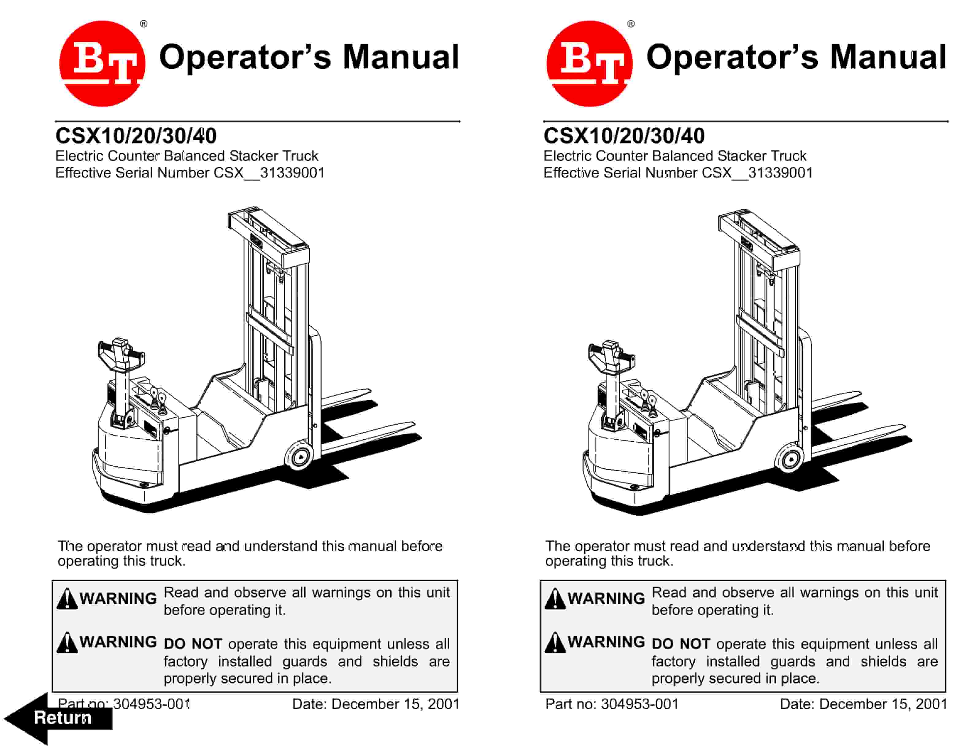
BT CSX Electric Counter Balanced Stacker Truck Operator Manual 304953-001
$20.00
BT Operator Manual PDF
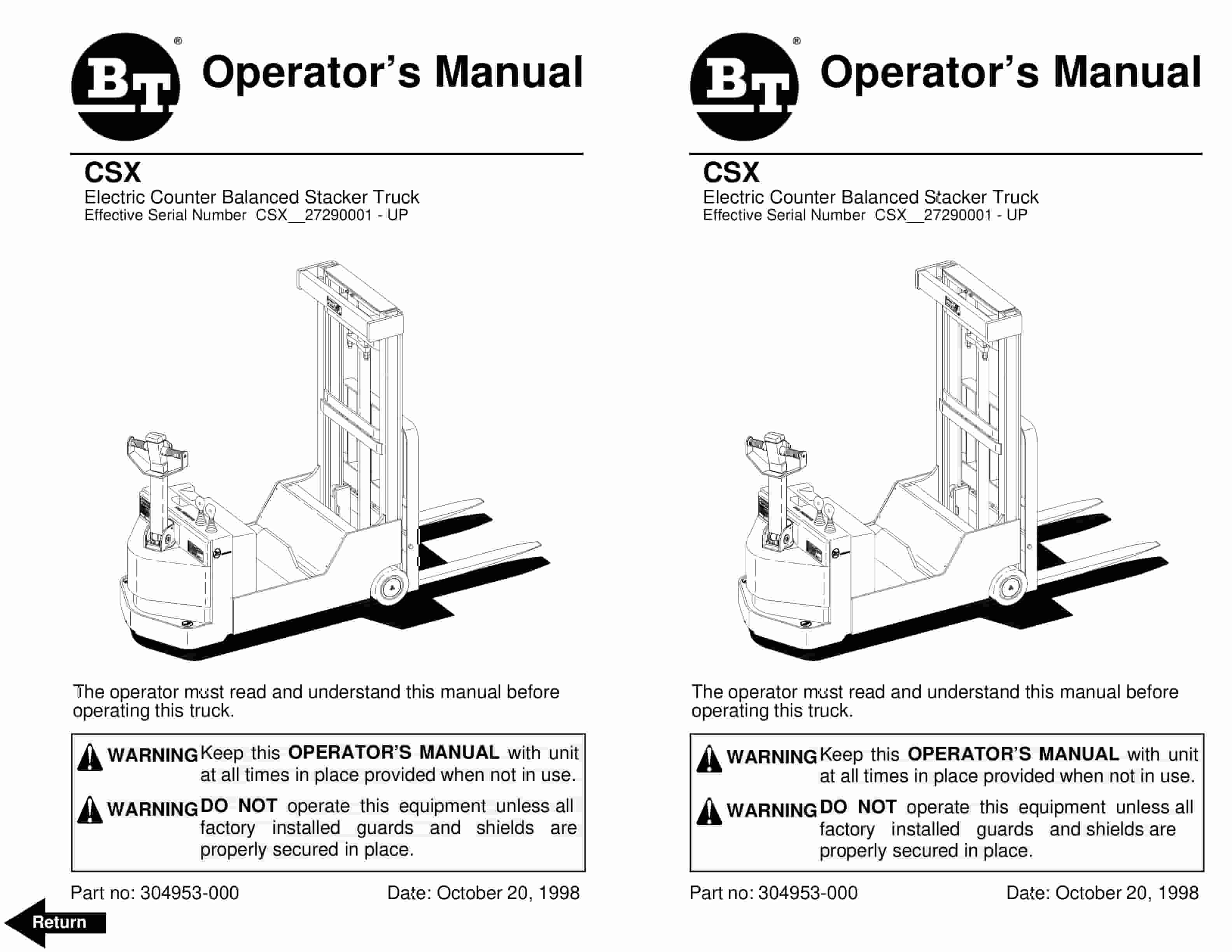
BT CSX Electric Counter Balanced Stacker Truck Operator Manual 304953-000
$20.00


