


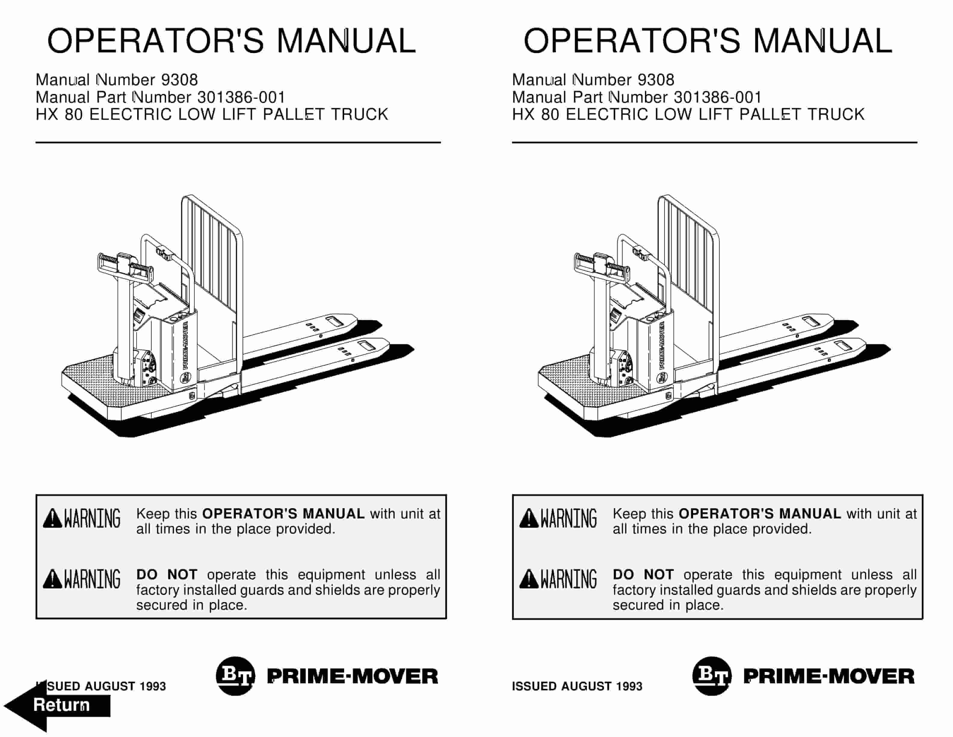
BT Operator Manual PDF
BT HT60W Warehouser Electric Low Lift Truck Operator Manual 300687-000
$20.00
BT Operator Manual PDF
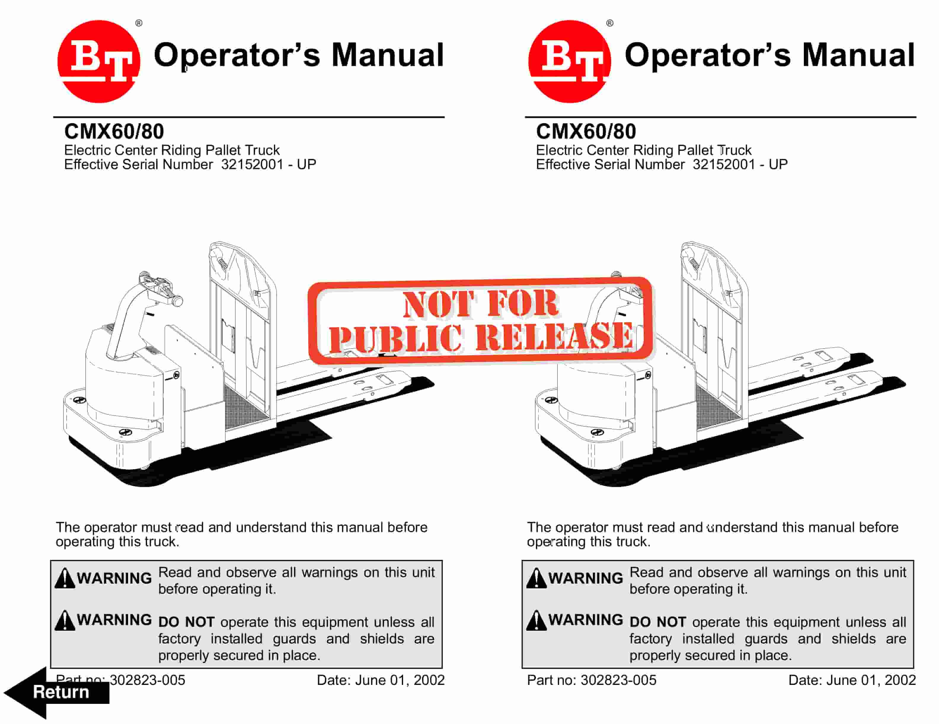
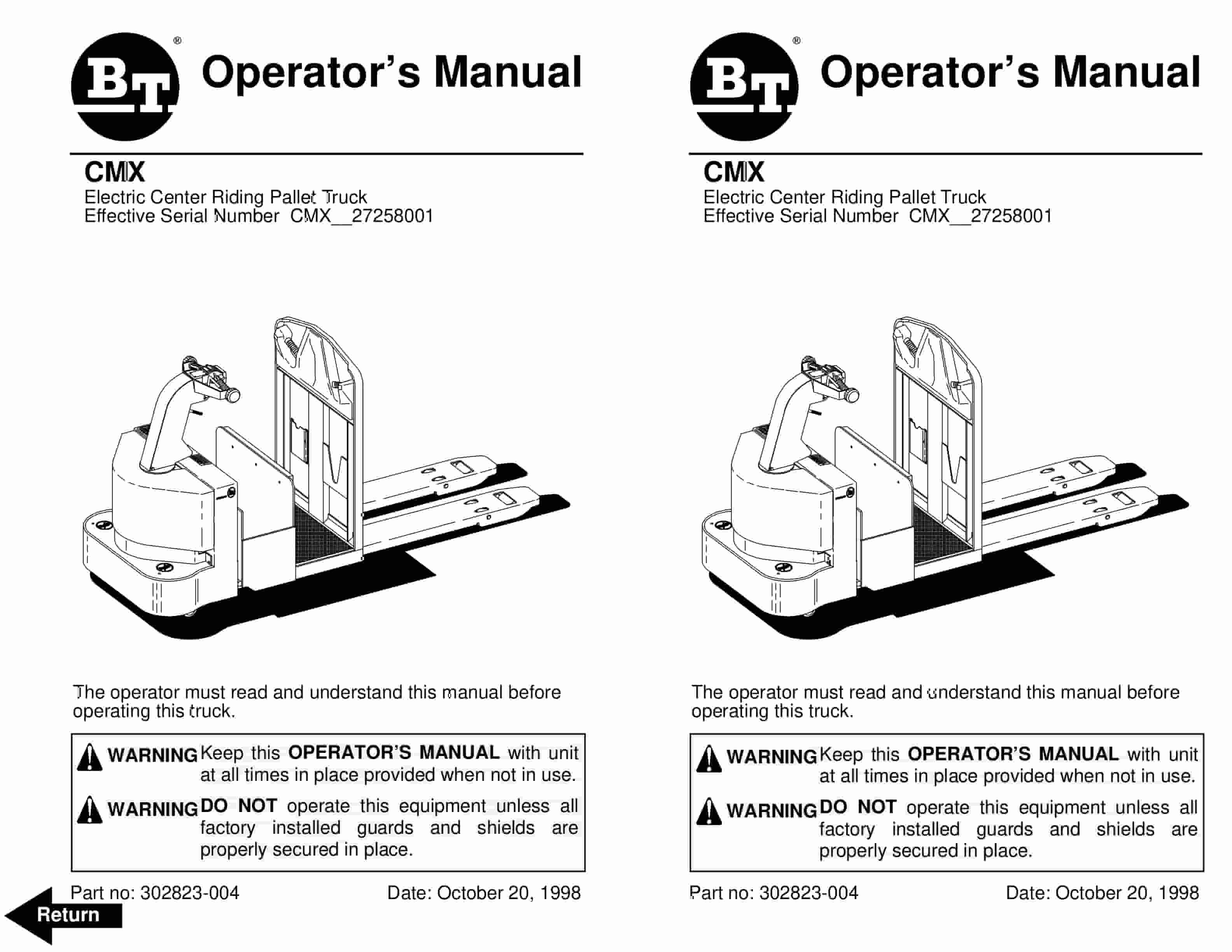
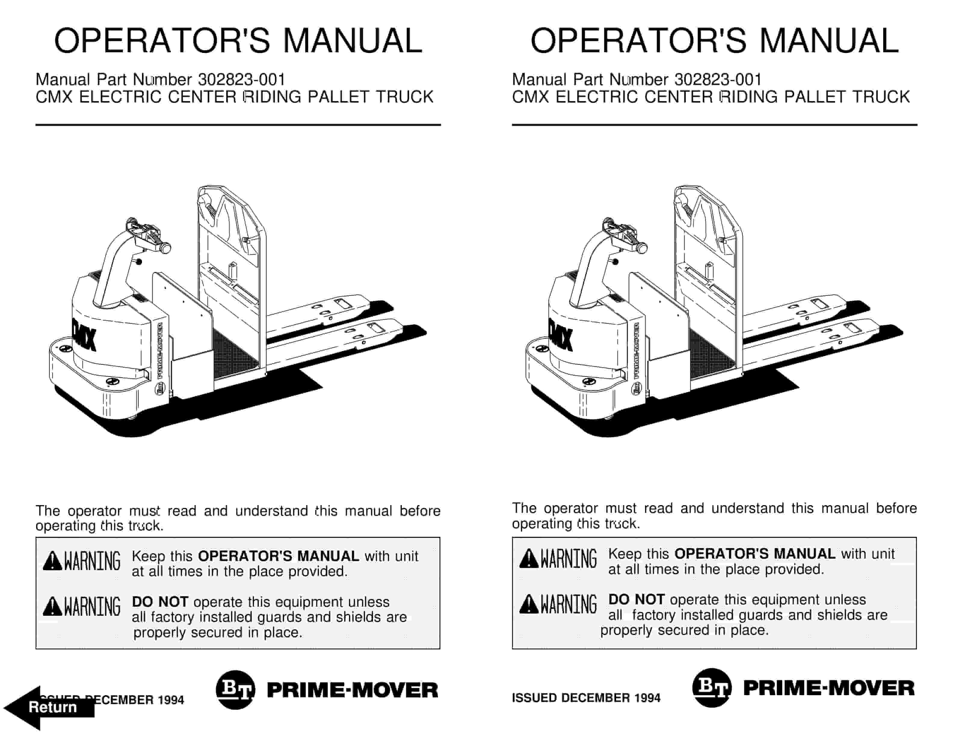
BT CMX60, CMX80 Electric Center Riding Pallet Truck Operator Manual 302823-005
$20.00
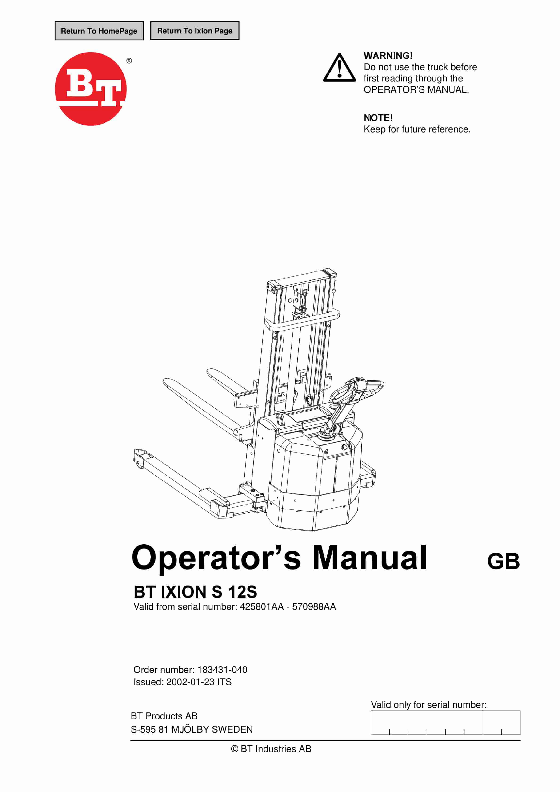
BT Operator Manual PDF
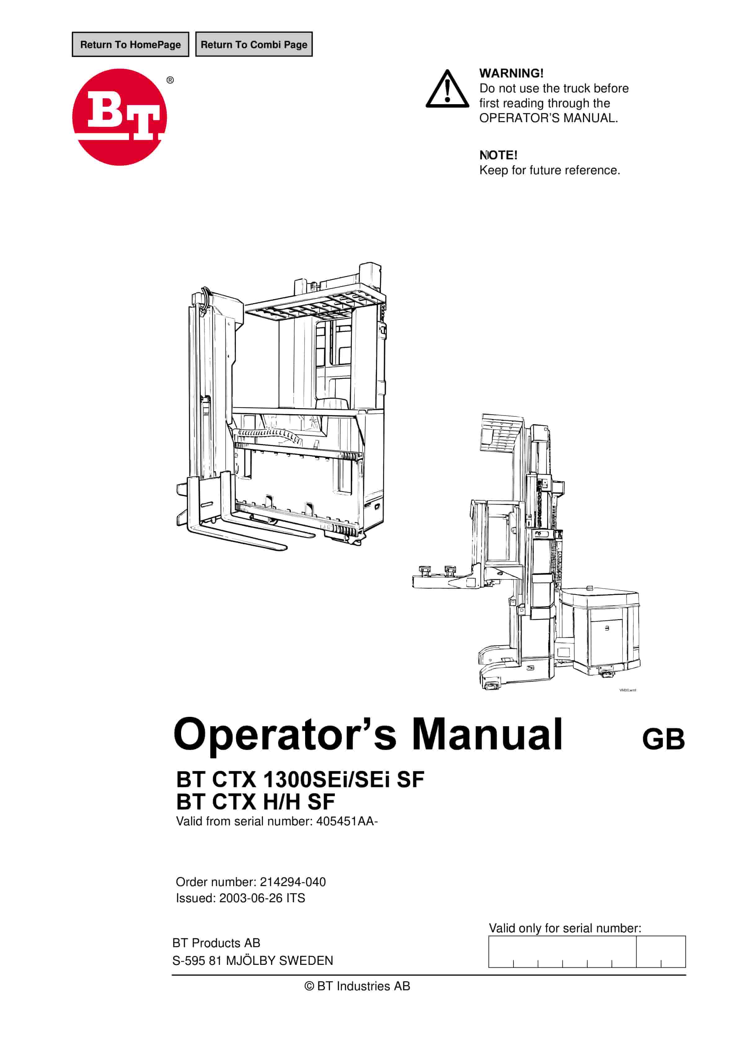
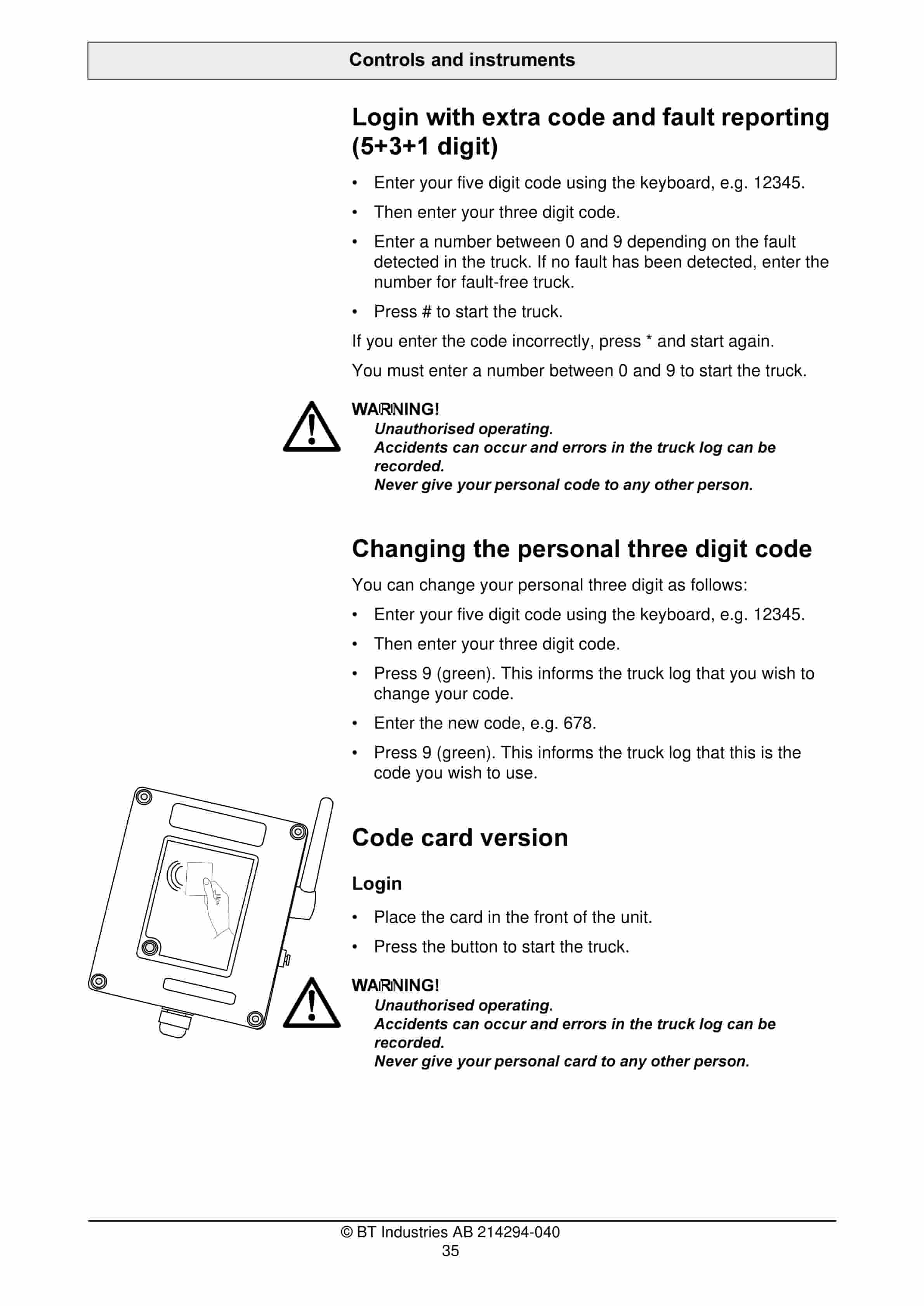
BT CTX1300SEi, CTX1300SEi SF, CTX H, CTX H SF Operator Manual 214294-040
$20.00