No products in the cart.
Return to shop
$20.00
BT Operator Manual PDF
BT CMX Electric Center Riding Pallet Truck Operator Manual 302823-004
BT CMX60, CMX80 Electric Center Riding Pallet Truck Operator Manual 302823-005
BT CMX Electric Center Riding Pallet Truck Operator Manual 302823-002
BT CMX Electric Center Riding Pallet Truck Operator Manual 308063-000
BT IXION S 12S Operator Manual 183431-040
BT IXION S 10, S 12 Operator Manual 182417-040
BT LPE200 Operator Manual 230509-040
BT LSF 1250, LSF 1250-8, LSF 1600 Operator Manual 173372-040
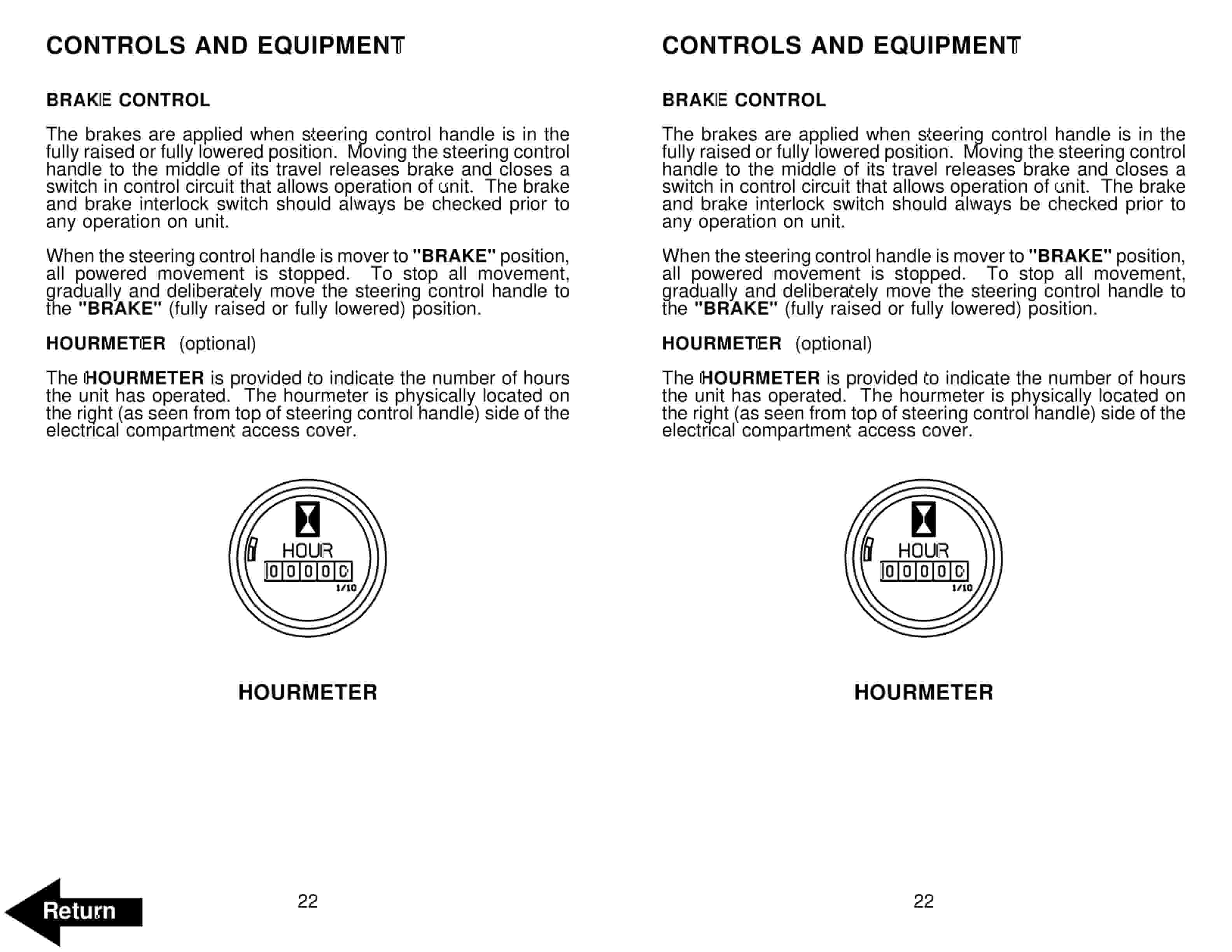
BT HX-65 Electric Low Lift Pallet Truck Operator Manual 301385-001
BT LAE240 Operator Manual 234918-040


