Caterpillar C3000 to C6500 Chassis and Mast Service Manual 99719-8C140
$50.00
- Type Of Manual: Service Manual
- Manual ID: 99719-8C140
- Number of Pages: 549
- Size: 44.2MB
- Format: PDF
-
Model List:
- C3000, C3500, CC4000, C4000, C5000, C5500, C6000, C6500
- 1. vol1
- 1.1. FOREWORD
- 1.1.1. Safety
- 1.1.2. Symbols and Abbreviations
- 1.1.3. Units
- 1.2. TABLE OF CONTENTS
- 1.3. Chapter 1 GENERAL INFORMATION
- 1.3.1. Model View
- 1.3.2. Truck Models Covered
- 1.3.3. Serial Number Locations
- 1.3.4. Dimensions
- 1.3.5. Technical Data
- 1.4. Chapter 2 COOLING SYSTEM
- 1.4.1. Specification
- 1.4.2. Structure
- 1.4.3. Removing Fan Belt
- 1.4.4. Installing Fan Belt
- 1.4.5. Inspecting and Adjusting Cooling System
- 1.5. Chapter 3 ELECTRICAL SYSTEM
- 1.5.1. Electrical Components and Wiring Outline
- 1.5.2. Console Box
- 1.5.3. Meter Panel
- 1.5.4. Main Electrical Components
- 1.5.5. Battery and Maintenance
- 1.5.6. Wire Color
- 1.5.7. Troubleshooting
- 1.5.8. Fuel Pressure Sensor Harness
- 1.5.9. Wiring Harness Service Parts
- 1.5.10. Electrical Wiring Diagram
- 1.6. Chapter 4 CONTROLLER
- 1.6.1. Outline
- 1.6.2. Main Functions of Controllers
- 1.6.3. Service Tool
- 1.6.4. Mast Interlock System
- 1.6.5. Driving Interlock System
- 1.6.6. Seat Belt Warning Light
- 1.6.7. Parking Brake Warning Buzzer and Light
- 1.6.8. Harness Codes
- 1.6.9. Controller Output Details
- 1.6.10. Truck Status Display and Troubleshooting
- 1.6.11. Common Diagnostic Codes
- 1.7. Chapter 5 POWER TRAIN
- 1.7.1. Removing and Installing Engine and Transmission Assembly
- 1.8. Chapter 6 POWERSHIFT TRANSMISSION
- 1.8.1. Structure
- 1.8.2. Removing Transmission
- 1.8.3. Installing Transmission
- 1.8.4. Disassembling Control Valve
- 1.8.5. Inspection and Repair After Disassembling Control Valve
- 1.8.6. Assembling Control Valve
- 1.8.7. Disassembling Input Shaft Assembly
- 1.8.8. Inspection and Repair After Disassembling Input Shaft Assembly
- 1.8.9. Disassembling Oil Pump Assembly
- 1.8.10. Inspection and Repair After Disassembling Oil Pump Assembly
- 1.8.11. Assembling Oil Pump
- 1.8.12. Inspection and Adjustment
- 1.8.13. Troubleshooting
- 1.8.14. Tightening Torque
- 1.8.15. Service Data
- 1.9. Chapter 7 FRONT AXLE AND REDUCTION DIFFERENTIAL
- 1.9.1. Structure
- 1.9.2. Removing and Installing Front Wheels
- 1.9.3. Removing Front Axle
- 1.9.4. Disassembling and Assembling Front Axle
- 1.9.5. Removing and Installing Reduction Differential
- 1.9.6. Disassembling and Assembling Reduction Differential
- 1.9.7. Disassembling and Assembling Reduction Differential
- 1.9.8. Troubleshooting
- 1.9.9. Service Data
- 1.10. Chapter 8 REAR AXLE
- 1.10.1. Structure
- 1.10.2. Removing Rear Wheels
- 1.10.3. Installing Rear Wheels
- 1.10.4. Removing Rear Wheels and Rear Axle Assembly
- 1.10.5. Installing Rear Wheels
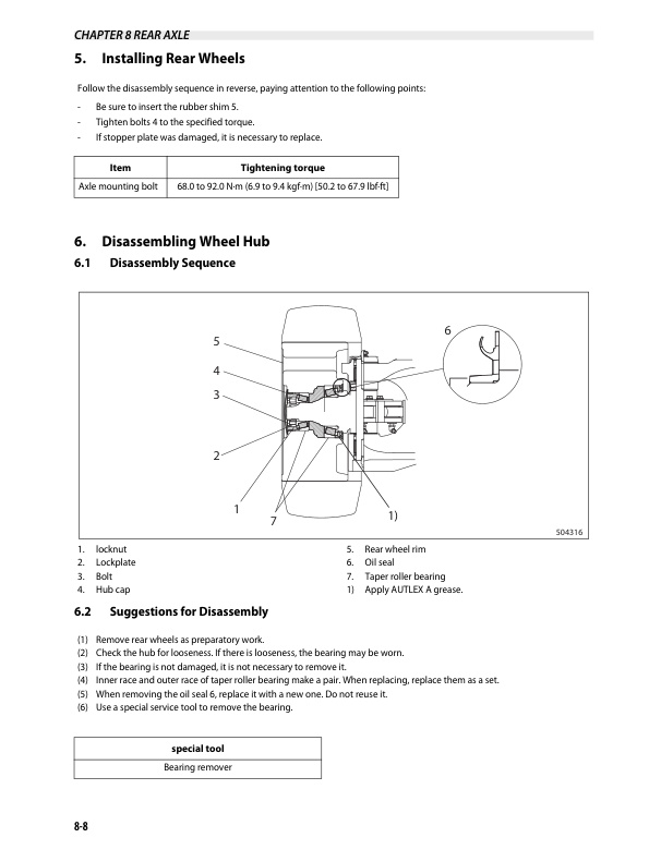
- 1.10.6. Disassembling Wheel Hub
- 1.10.7. Inspection and Repair After Disassembly
- 1.10.8. Assembling Wheel Hub
- 1.10.9. Disassembling Knuckle (King Pin)
- 1.10.10. Inspection and Repair After Disassembling Knuckle (King Pin)
- 1.10.11. Assembling Knuckle (King Pin)
- 1.10.12. Removing Steering Cylinder
- 1.10.13. Inspection and Repair After Disassembling Steering Cylinder
- 1.10.14. Assembling Steering Cylinder
- 1.10.15. Disassembling and Assembling Tie Rod
- 1.10.16. Assembling Tie Rod
- 1.10.17. Troubleshooting
- 1.10.18. Service Data
- 1.11. Chapter 9 BRAKE SYSTEM
- 1.11.1. Structure of Brake System
- 1.11.2. Structure of Wheel Brakes
- 1.11.3. Disassembling Master Cylinder
- 1.11.4. Inspection and Repair After Disassembling Master Cylinder
- 1.11.5. Assembling Master Cylinder
- 1.11.6. Disassembling Wheel Brakes
- 1.11.7. Inspection After Disassembling Wheel Brakes
- 1.11.8. Assembling Wheel Brakes
- 1.11.9. Assembling Wheel Cylinder
- 1.11.10. Inspection and Repair After Disassembling Wheel Cylinder
- 1.11.11. Assembling Wheel Cylinder
- 1.11.12. Inspecting and Adjusting Brake System
- 1.11.13. Troubleshooting
- 1.11.14. Service Data
- 1.12. Chapter 10 STEERING SYSTEM
- 1.12.1. Structure and Function
- 1.12.2. Disassembling and Assembling Pipes and Hoses
- 1.12.3. Disassembling Steering Wheel and Steering Valve
- 1.12.4. Installation
- 1.12.5. Removing Steering Valve
- 1.12.6. Installing Steering Valve
- 1.12.7. Disassembling Tilt Lock Lever
- 1.12.8. Assembling Tilt Lock Lever
- 1.12.9. Disassembling Steering Valve
- 1.12.10. Inspection After Disassembly
- 1.12.11. Assembling Steering Valve
- 1.12.12. Troubleshooting
- 1.12.13. Service Data
- 1.13. Chapter 11 HYDRAULIC SYSTEM
- 1.13.1. Structure
- 1.13.2. Removing Hydraulic Pump
- 1.13.3. Installing Hydraulic Pump
- 1.13.4. Disassembling Hydraulic Pump
- 1.13.5. Inspection and Repair After Disassembling Hydraulic Pump
- 1.13.6. Assembling Hydraulic Pump
- 1.13.7. Inspection and Adjustment After Assembling Hydraulic Pump
- 1.13.8. Removing Lift Cylinders (Simplex Mast)
- 1.13.9. Installing Lift Cylinder (Simplex Mast)
- 1.13.10. Removing Lift Cylinder (Duplex and Triplex Mast)
- 1.13.11. Installing Lift Cylinder (Duplex and Triplex Mast)
- 1.13.12. Disassembling Lift Cylinder (First Lift Cylinder for Duplex Mast and Triplex Mast)
- 1.13.13. Inspection After Disassembly (First Lift Cylinder for Duplex Mast and Triplex Mast)
- 1.13.14. Assembling Lift Cylinder (First Lift Cylinder for Duplex Mast and Triplex Mast)
- 1.13.15. Disassembling Lift Cylinder (Second Cylinder for Simplex Mast and Triplex Mast)
- 1.13.16. Inspection After Disassembling Lift Cylinder (Second Cylinder for Simplex Mast and Triplex Mast)
- 1.13.17. Assembling Lift Cylinder (Second Cylinder for Simplex Mast and Triplex Mast)
- 1.13.18. Disassembling Lift Cylinder (Second Lift Cylinder for Duplex Mast)
- 1.13.19. Inspection After Disassembling Lift Cylinder (Second Lift Cylinder for Duplex Mast)
- 1.13.20. Assembling Lift Cylinder (Second Lift Cylinder for Duplex Mast)
- 1.13.21. Removing Tilt Cylinder
- 1.13.22. Installing Tilt Cylinder
- 1.13.23. Disassembling Tilt Cylinder
- 1.13.24. Assembling Tilt Cylinder
- 1.13.25. Piping
- 1.13.26. Removing Suction Strainer and Return Filter
- 1.13.27. Inspecting Suction Strainer and Return Filter
- 1.13.28. Installing Suction Strainer and Return Filter
- 1.13.29. Hydraulic System Adjustment
- 1.13.30. Troubleshooting
- 1.13.31. Service Data
- 1.13.32. MC Control Valve
- 1.13.33. Removing MC Control Valve
- 1.13.34. Installing MC Control Valve
- 1.13.35. Disassembly Sequence of Valve of Inlet Cover Section
- 1.13.36. Disassembly Sequence of Combination Section (Lift Valve)
- 1.13.37. Disassembly Sequence of Combination Section (Tilt Valve)
- 1.13.38. Disassembly Sequence of End Cover Section (Unloader Valve)
- 1.13.39. Inspection and Repair After Disassembling MC Control Valve
- 1.13.40. Assembling MC Control Valve
- 1.14. Chapter 12 MAST AND FORKS
- 1.14.1. Simplex Mast
- 1.14.2. Duplex Mast
- 1.14.3. Triplex Mast
- 1.15. Chapter 13 SERVICE DATA
- 1.15.1. Maintenance Schedule
- 1.15.2. Tightening Torques for Standard Bolts and Nuts
- 1.15.3. Periodic Replacement Parts
- 1.15.4. Lubrication Instructions
- 1.15.5. Special tools
- 1.16. Chapter 14 APPENDIX
- 1.16.1. Sulfur Smell from the Exhaust System
- 1.16.2. High Speed Cooling (Option)
- 1.16.3. Corrugated Square Fin Cove Option
- 1.16.4. Information on the Foot Directional Control System (Option)
- 1.16.5. Ground Speed Control or Travel Speed Limit Option
- 1.16.6. DOT-Lok MPE Installation and Programming
- 1.16.7. Propane Fuel Tank Basics
- 1.16.8. Heavy Duty Upper Wear Pad Kit
- 1.17. Back cover
- 1.18. Rear cover
- 2. vol2
- 2.1. FOREWORD
- 2.1.1. Safety
- 2.1.2. Symbols and Abbreviations
- 2.1.3. Units
- 2.2. TABLE OF CONTENTS
- 2.3. Chapter 1 GENERAL INFORMATION
- 2.3.1. Model View
- 2.3.2. Truck Models Covered
- 2.3.3. Serial Number Locations
- 2.3.4. Dimensions
- 2.3.5. Technical Data
- 2.4. Chapter 2 COOLING SYSTEM
- 2.4.1. Specification
- 2.4.2. Structure
- 2.4.3. Removing Fan Belt
- 2.4.4. Installing Fan Belt
- 2.4.5. Inspecting and Adjusting Cooling System
- 2.5. Chapter 3 ELECTRICAL SYSTEM
- 2.5.1. Electrical Components and Wiring Outline
- 2.5.2. Console Box
- 2.5.3. Meter Panel
- 2.5.4. Main Electrical Components
- 2.5.5. Battery and Maintenance
- 2.5.6. Wire Color
- 2.5.7. Troubleshooting
- 2.5.8. Fuel Pressure Sensor Harness
- 2.5.9. Wiring Harness Service Parts
- 2.5.10. Electrical Wiring Diagram
- 2.6. Chapter 4 CONTROLLER
- 2.6.1. Outline
- 2.6.2. Main Functions of Controllers
- 2.6.3. Service Tool
- 2.6.4. Mast Interlock System
- 2.6.5. Driving Interlock System
- 2.6.6. Seat Belt Warning Light
- 2.6.7. Parking Brake Warning Buzzer and Light
- 2.6.8. Harness Codes
- 2.6.9. Controller Output Details
- 2.6.10. Truck Status Display and Troubleshooting
- 2.6.11. Common Diagnostic Codes
- 2.7. Chapter 5 POWER TRAIN
- 2.7.1. Removing and Installing Engine and Transmission Assembly
- 2.8. Chapter 6 POWERSHIFT TRANSMISSION
- 2.8.1. Structure
- 2.8.2. Removing Transmission
- 2.8.3. Installing Transmission
- 2.8.4. Disassembling Control Valve
- 2.8.5. Inspection and Repair After Disassembling Control Valve
- 2.8.6. Assembling Control Valve
- 2.8.7. Disassembling Input Shaft Assembly
- 2.8.8. Inspection and Repair After Disassembling Input Shaft Assembly
- 2.8.9. Disassembling Oil Pump Assembly
- 2.8.10. Inspection and Repair After Disassembling Oil Pump Assembly
- 2.8.11. Assembling Oil Pump
- 2.8.12. Inspection and Adjustment
- 2.8.13. Troubleshooting
- 2.8.14. Tightening Torque
- 2.8.15. Service Data
- 2.9. Chapter 7 FRONT AXLE AND REDUCTION DIFFERENTIAL
- 2.9.1. Structure
- 2.9.2. Removing and Installing Front Wheels
- 2.9.3. Removing Front Axle
- 2.9.4. Disassembling and Assembling Front Axle
- 2.9.5. Removing and Installing Reduction Differential
- 2.9.6. Disassembling and Assembling Reduction Differential
- 2.9.7. Disassembling and Assembling Reduction Differential
- 2.9.8. Troubleshooting
- 2.9.9. Service Data
- 2.10. Chapter 8 REAR AXLE
- 2.10.1. Structure
- 2.10.2. Removing Rear Wheels
- 2.10.3. Installing Rear Wheels
- 2.10.4. Removing Rear Wheels and Rear Axle Assembly
- 2.10.5. Installing Rear Wheels
- 2.10.6. Disassembling Wheel Hub
- 2.10.7. Inspection and Repair After Disassembly
- 2.10.8. Assembling Wheel Hub
- 2.10.9. Disassembling Knuckle (King Pin)
- 2.10.10. Inspection and Repair After Disassembling Knuckle (King Pin)
- 2.10.11. Assembling Knuckle (King Pin)
- 2.10.12. Removing Steering Cylinder
- 2.10.13. Inspection and Repair After Disassembling Steering Cylinder
- 2.10.14. Assembling Steering Cylinder
- 2.10.15. Disassembling and Assembling Tie Rod
- 2.10.16. Assembling Tie Rod
- 2.10.17. Troubleshooting
- 2.10.18. Service Data
- 2.11. Chapter 9 BRAKE SYSTEM
- 2.11.1. Structure of Brake System
- 2.11.2. Structure of Wheel Brakes
- 2.11.3. Disassembling Master Cylinder
- 2.11.4. Inspection and Repair After Disassembling Master Cylinder
- 2.11.5. Assembling Master Cylinder
- 2.11.6. Disassembling Wheel Brakes
- 2.11.7. Inspection After Disassembling Wheel Brakes
- 2.11.8. Assembling Wheel Brakes
- 2.11.9. Assembling Wheel Cylinder
- 2.11.10. Inspection and Repair After Disassembling Wheel Cylinder
- 2.11.11. Assembling Wheel Cylinder
- 2.11.12. Inspecting and Adjusting Brake System
- 2.11.13. Troubleshooting
- 2.11.14. Service Data
- 2.12. Chapter 10 STEERING SYSTEM
- 2.12.1. Structure and Function
- 2.12.2. Disassembling and Assembling Pipes and Hoses
- 2.12.3. Disassembling Steering Wheel and Steering Valve
- 2.12.4. Installation
- 2.12.5. Removing Steering Valve
- 2.12.6. Installing Steering Valve
- 2.12.7. Disassembling Tilt Lock Lever
- 2.12.8. Assembling Tilt Lock Lever
- 2.12.9. Disassembling Steering Valve
- 2.12.10. Inspection After Disassembly
- 2.12.11. Assembling Steering Valve
- 2.12.12. Troubleshooting
- 2.12.13. Service Data
- 2.13. Chapter 11 HYDRAULIC SYSTEM
- 2.13.1. Structure
- 2.13.2. Removing Hydraulic Pump
- 2.13.3. Installing Hydraulic Pump
- 2.13.4. Disassembling Hydraulic Pump
- 2.13.5. Inspection and Repair After Disassembling Hydraulic Pump
- 2.13.6. Assembling Hydraulic Pump
- 2.13.7. Inspection and Adjustment After Assembling Hydraulic Pump
- 2.13.8. Removing Lift Cylinders (Simplex Mast)
- 2.13.9. Installing Lift Cylinder (Simplex Mast)
- 2.13.10. Removing Lift Cylinder (Duplex and Triplex Mast)
- 2.13.11. Installing Lift Cylinder (Duplex and Triplex Mast)
- 2.13.12. Disassembling Lift Cylinder (First Lift Cylinder for Duplex Mast and Triplex Mast)
- 2.13.13. Inspection After Disassembly (First Lift Cylinder for Duplex Mast and Triplex Mast)
- 2.13.14. Assembling Lift Cylinder (First Lift Cylinder for Duplex Mast and Triplex Mast)
- 2.13.15. Disassembling Lift Cylinder (Second Cylinder for Simplex Mast and Triplex Mast)
- 2.13.16. Inspection After Disassembling Lift Cylinder (Second Cylinder for Simplex Mast and Triplex Mast)
- 2.13.17. Assembling Lift Cylinder (Second Cylinder for Simplex Mast and Triplex Mast)
- 2.13.18. Disassembling Lift Cylinder (Second Lift Cylinder for Duplex Mast)
- 2.13.19. Inspection After Disassembling Lift Cylinder (Second Lift Cylinder for Duplex Mast)
Caterpillar Service Manual PDF
Caterpillar 1204E Diesel Engine Operation and Maintenance Manual Service Manual 99799-64105
Caterpillar Service Manual PDF
Caterpillar 2EC15 to 2EC30 MicroCommand II Control Service Manual SENB8604-02
Caterpillar Service Manual PDF
Caterpillar 4G63, 4G64, 6G72 Liquefied Petroleum Gas Supplement Service Manual 99719-84130
Caterpillar Service Manual PDF
Caterpillar 1204E Diesel Engine Systems Operation Testing and Adjusting Service Manual 99799-64103
Caterpillar Service Manual PDF
Caterpillar 1204F Diesel Engine Troubleshooting Service Manual 99799-67104
Caterpillar Service Manual PDF
Caterpillar 4G63, 4G64 Fuel System Supplement Service Manual 99729-85110
Caterpillar Service Manual PDF
Caterpillar 1204F Diesel Engine Service Manual SCEEA-AT15F-200
Caterpillar Service Manual PDF
Caterpillar 1.4 Liter (4G33) to 3.0 Liter (6G72) LP Gas Supplement Service Manual SENB8531
Caterpillar Service Manual PDF
Caterpillar 1204F Diesel Engine Systems Operation Testing and Adjusting Service Manual 99799-67103
Caterpillar Service Manual PDF
Caterpillar 1.4 Liter (4G33) Gasoline Engine Service Manual SENB8525
