(C), NR16-20N3, NR16-25N3H(X), NRM20-25N3, NTD13-15N3 Service Manual SM21GBRE1AC3 1")
(C), NR16-20N3, NR16-25N3H(X), NRM20-25N3, NTD13-15N3 Service Manual SM21GBRE1AC3 2")
(C), NR16-20N3, NR16-25N3H(X), NRM20-25N3, NTD13-15N3 Service Manual SM21GBRE1AC3 3")
(C), NR16-20N3, NR16-25N3H(X), NRM20-25N3, NTD13-15N3 Service Manual SM21GBRE1AC3 4")
(C), NR16-20N3, NR16-25N3H(X), NRM20-25N3, NTD13-15N3 Service Manual SM21GBRE1AC3 5")

Caterpillar Service Manual PDF
Caterpillar 2EC15 to 2EC30 MicroCommand II Control Service Manual SENB8609
Caterpillar Service Manual PDF
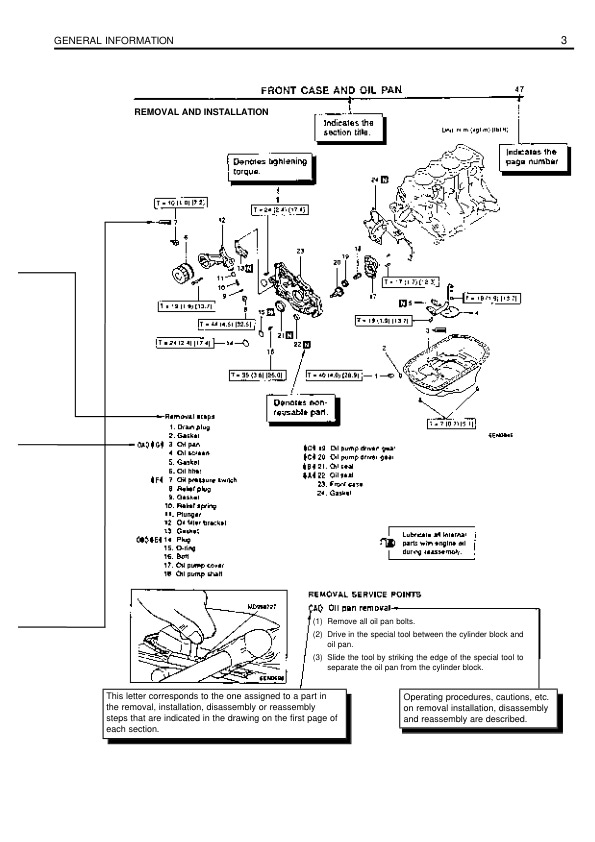
Caterpillar 4G63, 4G64 Gasoline Engine Service Manual 99729-84120

Caterpillar Service Manual PDF
Caterpillar 2EC15 to 2EC30 MicroCommand II Control Service Manual SENB8604-02
Caterpillar Service Manual PDF
Caterpillar 1204F Diesel Engine Troubleshooting Service Manual 99799-67104

Caterpillar Service Manual PDF
Caterpillar 1204F Diesel Engine Systems Operation Testing and Adjusting Service Manual 99799-67103
(C),%20NR16-20N3,%20NR16-25N3H(X),%20NRM20-25N3,%20NTD13-15N3%20Service%20Manual%20SM21GBRE1AC3&url=https://ownersmanualpdf.net/docs/caterpillar-nr12-14n3lc-nr16-20n3-nr16-25n3hx-nrm20-25n3-ntd13-15n3-service-manual-sm21gbre1ac3/&media=https://ownersmanualpdf.net/wp-content/uploads/2025/10/caterpillar-nr12-14n3lc-nr16-20n3-nr16-25n3hx-nrm20-25n3-ntd13-15n3-service-manual-sm21gbre1ac3-1.jpg)
Caterpillar Service Manual PDF
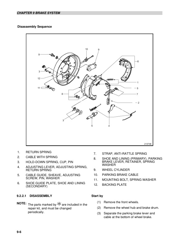
Caterpillar 2P3000 to 2PD7000, GP15NM-35NM Chassis and Mast Service Manual 99719-8M110
Caterpillar Service Manual PDF
Caterpillar 1204F Diesel Engine Operation and Maintenance Manual Service Manual 99799-67105
Caterpillar Service Manual PDF
Caterpillar 4G63, 4G64, 6G72 Liquefied Petroleum Gas Supplement Service Manual 99719-84130

Caterpillar Service Manual PDF
Caterpillar 1204E Diesel Engine Systems Operation Testing and Adjusting Service Manual 99799-64103