Caterpillar NOL10P Service Manual SM23GBEPL1C1
$50.00
- Type Of Manual: Service Manual
- Manual ID: SM23GBEPL1C1
- Number of Pages: 158
- Size: 5.7MB
- Format: PDF
-
Model List:
- NOL10P
- 1. GENERAL INFORMATION AND TECHNICAL DATA
- 1.1. Introduction
- 1.1.1. General
- 1.1.2. The trucks
- 1.1.3. Genuine Parts
- 1.1.4. Authorised service personnel
- 1.1.5. Symbol key
- 1.2. Safety
- 1.2.1. General
- 1.2.2. Safety instructions
- 1.2.3. Truck modification
- 1.2.4. Lifting the truck
- 1.2.5. Welding on truck
- 1.3. Environmental considerations
- 1.3.1. We respect the environment
- 1.4. Preparations
- 1.4.1. Service
- 1.4.2. Troubleshooting
- 1.5. Truck data
- 1.5.1. Machine plates
- 1.5.2. Safety and warning signs
- 1.5.3. Explanation of symbols
- 1.5.4. Type designation
- 1.5.5. Truck types
- 1.5.6. Dimensions and weights
- 1.6. Component placement
- 1.6.1. SLOP 24V
- 1.7. Component specification
- 1.7.1. Drive motor
- 1.7.2. Electric brake
- 1.7.3. Gearbox
- 1.7.4. Hydraulic unit
- 1.7.5. Control system for traction and pump motors
- 1.7.6. Steering servo motor
- 1.7.7. Controller system for steering
- 1.8. Recommended consumable materials
- 1.8.1. Oil and grease types
- 1.9. Code explanations
- 1.9.1. Colour codes for wiring diagrams
- 1.9.2. Designations for electrical components in electrical diagram
- 1.9.3. Standard abbreviations and units
- 1.9.4. Acronyms and abbreviations
- 2. SPECIAL TOOLS
- 2.1. List of tools
- 3. SERVICE
- 3.1. Service schedule / inspection
- 3.1.1. Introduction
- 3.1.2. Safety
- 3.1.3. Service schedule explanation
- 3.1.4. Inspection daily / monthly / PDI and commissioning
- 3.1.5. First service (200 hours)
- 3.1.6. Main service
- 3.1.7. Extra service inspections
- 3.1.8. Service inspection
- 3.1.9. Dye penetration inspection instruction
- 3.2. Service schedule
- 3.3. Lubrication
- 3.3.1. Recommended lubricants
- 3.3.2. Symbol key, lubrication chart
- 3.3.3. Lubrication chart
- 4. CHASSIS
- 4.1. Design and function
- 4.1.1. Machine housing
- 4.1.2. Overhead guard
- 4.1.3. Battery locking
- 4.1.4. Covers and panels
- 4.2. Repair and maintenance instructions
- 4.2.1. Before work is performed
- 4.2.2. Removal and installation of the overhead guard
- 4.2.3. Panels and housing
- 4.2.4. Removal and installation of the battery rollers
- 4.2.5. Remove and install the foot plate
- 4.2.6. Tilt the truck before changing wheels
- 4.2.7. Replacing the load wheels, SLOP 24V
- 5. DRIVE UNIT
- 5.1. Design and function
- 5.1.1. Description
- 5.1.2. Drive motor
- 5.1.3. Gearbox
- 5.1.4. Drive wheel
- 5.2. Repair and maintenance instructions
- 5.2.1. Before work is performed
- 5.2.2. Servicing and maintenance
- 5.3. Drive unit, SLOP 24V
- 5.3.1. Traction motor
- 5.3.2. Gearbox
- 5.3.3. Drive wheels
- 5.4. Diagnostics and troubleshooting
- 5.4.1. Troubleshooting
- 5.4.2. Troubleshooting chart
- 6. MAST SYSTEM
- 6.1. Design and function
- 6.1.1. Fixation of the mast
- 6.1.2. Operators platform
- 6.1.3. Mast switch in mast
- 6.2. Repair and maintenance instructions
- 6.2.1. Before work is performed
- 6.2.2. Operators platform
- 6.2.3. Fork carriage
- 6.2.4. Lift chains
- 6.2.5. Control of initial lift stroke
- 6.2.6. Inspection of forks
- 6.3. Diagnostics and troubleshooting
- 6.3.1. Troubleshooting
- 7. STEERING
- 7.1. Design and function
- 7.1.1. General
- 7.1.2. Feedback sensors
- 7.1.3. Communication between the servo components
- 7.2. Repair and maintenance instructions
- 7.2.1. Before work is performed
- 7.2.2. Steering wheel
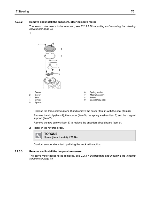
- 7.2.3. Steering servo motor
- 7.2.4. Remove and install the zero position sensor
- 7.2.5. Adjustments and tests
- 7.3. Diagnostics and troubleshooting
- 8. HYDRAULIC SYSTEM
- 8.1. Design and function
- 8.1.1. Description, SLOP 24V
- 8.1.2. Functions
- 8.1.3. Hydraulic diagram
- 8.1.4. Hydraulic unit, compact, SLOP 24V
- 8.1.5. Cylinders
- 8.1.6. Conduit components
- 8.1.7. Other components
- 8.1.8. Hydraulic oil
- 8.2. Repair and maintenance instructions
- 8.2.1. Before work is performed
- 8.2.2. General rules
- 8.2.3. Installation
- 8.2.4. Connections
- 8.2.5. Dismounting and mounting of hydraulic hoses
- 8.3. Hydraulic unit, compact, SLOP 24V
- 8.3.1. Dismounting and mounting
- 8.3.2. Start-up
- 8.3.3. Replacing the filter
- 8.3.4. Changing the oil
- 8.3.5. Checking the hydraulic oil level
- 8.3.6. Hydraulic motor
- 8.3.7. Pump, hydraulic unit
- 8.3.8. Hydraulic unit valves
- 8.4. Diagnostics and troubleshooting
- 8.4.1. TruckTool
- 8.4.2. Troubleshooting
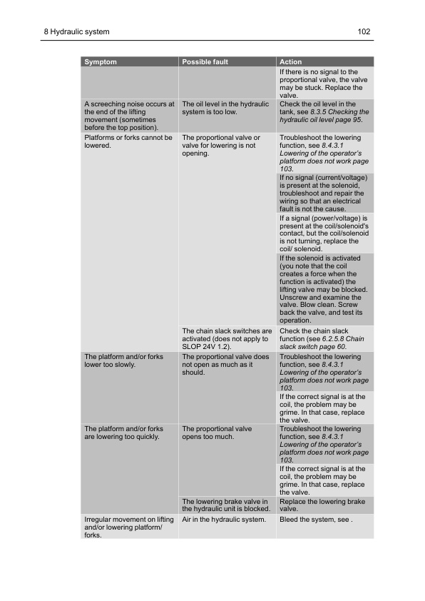
- 8.4.3. Troubleshooting, hydraulics functions, SLOP 24V
- 9. CYLINDERS
- 9.1. Design and function
- 9.1.1. Descriptions
- 9.1.2. Damping
- 9.1.3. Hose break valve
- 9.2. Repair and maintenance instructions
- 9.2.1. Before work is performed
- 9.2.2. Bleeding of the hydraulic cylinders without a bleed air screw
- 9.2.3. Bleeding of the hydraulic cylinders with an air bleed screw
- 9.2.4. Work with hose break valve/lowering brake valve in cylinders
- 9.2.5. Replace seals, lift cylinder
- 9.3. Cylinders, SLOP 24V
- 9.3.1. Dismounting and mounting, lift cylinder
- 9.3.2. Dismounting and mounting, initial cylinder (option)
- 10. ELECTRICAL SYSTEM
- 10.1. Introduction
- 10.1.1. Overview of components
- 10.1.2. CAN bus communication
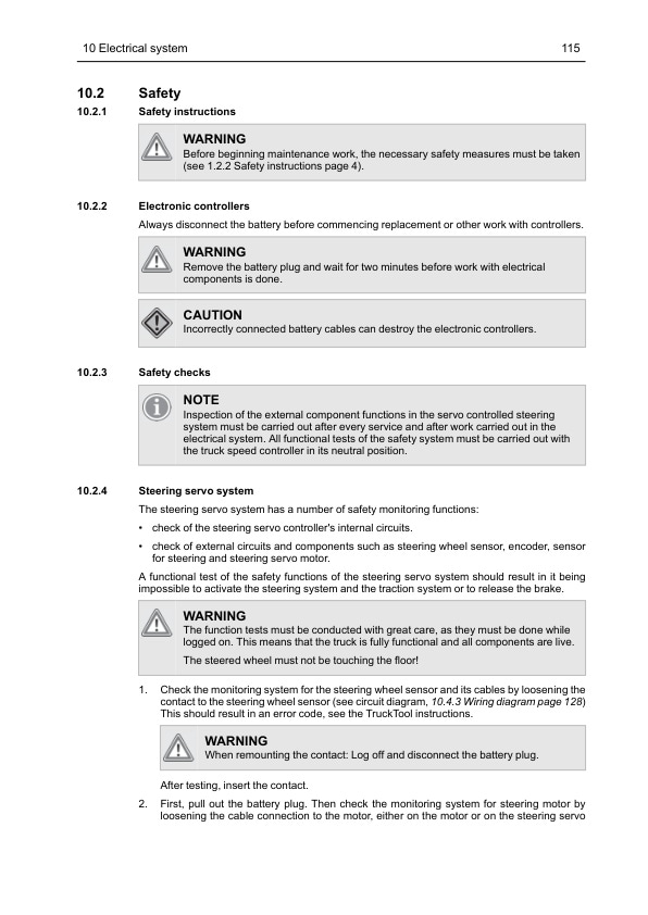
- 10.2. Safety
- 10.2.1. Safety instructions
- 10.2.2. Electronic controllers
- 10.2.3. Safety checks
- 10.2.4. Steering servo system
- 10.2.5. Hydraulic system
- 10.2.6. Traction speed system
- 10.2.7. Sensors
- 10.2.8. Safety controls, weight measurement system
- 10.2.9. Speed limits
- 10.3. Design and function
- 10.3.1. Battery replacement
- 10.3.2. Battery capacity
- 10.3.3. VCM (Vehicle Control Module) (truck computer)
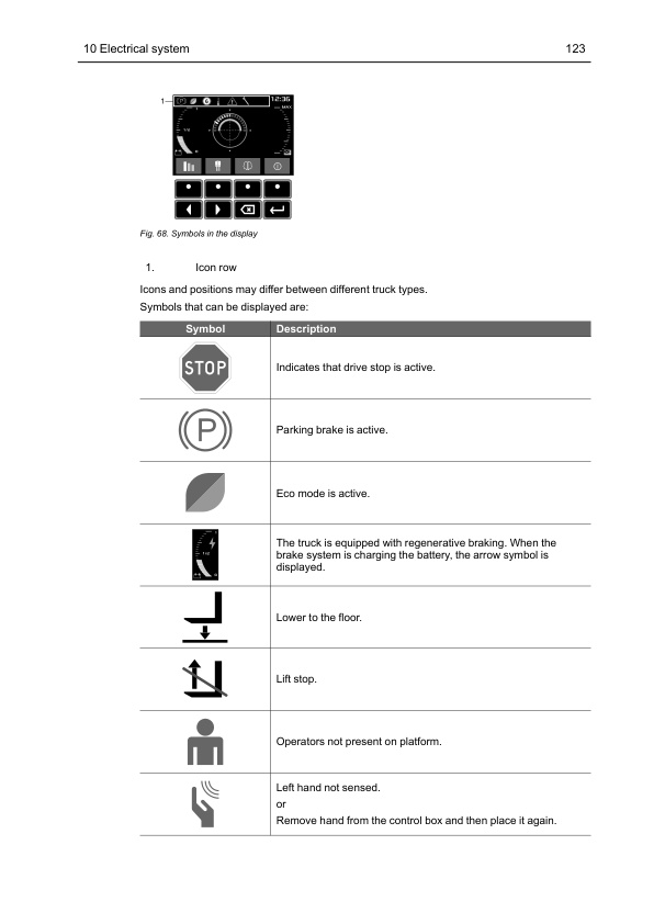
- 10.3.4. Display and icon panel
- 10.3.5. CMC (Combi Motor Controller)
- 10.3.6. EPS (Electrical Power Steering) controller
- 10.3.7. Hydraulic system
- 10.3.8. Brake system
- 10.3.9. Traction system
- 10.3.10. Connector specifications
- 10.4. Repair and maintenance instructions
- 10.4.1. Before work is performed
- 10.4.2. Connectors in cold store
- 10.4.3. Wiring diagram
- 10.4.4. Insulation test
- 10.4.5. Remove and install the VCM
- 10.4.6. Remove and install the multi function display (HMI-20)
- 10.4.7. Remove and install the safety sensors
- 10.4.8. TruckTool
- 10.5. Diagnostics and troubleshooting
- 11. SPEED CONTROL AND BRAKE SYSTEMS
- 11.1. Design and function
- 11.1.1. General
- 11.1.2. Speed and brake control
- 11.1.3. Electric brakes
- 11.1.4. Brake button
- 11.1.5. Motor brake
- 11.2. Repair and maintenance instructions
- 11.2.1. Before work is performed
- 11.2.2. Speed Controller
- 11.2.3. Brake button
- 11.2.4. Removal and installation of the left hand control
- 11.2.5. Electric brakes
- 11.3. Diagnostics and troubleshooting
- 11.3.1. Troubleshoot the speed controller
- 11.3.2. Troubleshoot the brake
- 12. MISCELLANEOUS
- 12.1. Stability support system, Cornering control
- 12.1.1. Speed restriction based on the steering angle
- 12.1.2. Dynamic cornering control
- 12.1.3. Settings DCC
- 12.2. Increased drive speed (option)
- 12.2.1. Design and function
- 12.2.2. Activation of Increased drive speed
- 12.2.3. Calibration of Weight system
- 12.3. Walk beside, option for SLOP 24V
- 12.3.1. Design and function
- 12.3.2. Activation Walk beside option
- 12.3.3. Setting the speed
- 12.4. Step warning
- 12.4.1. Design and function
- 12.4.2. Activation Step out warning option
- 12.5. PPS, Personnel Protection System
Caterpillar Service Manual PDF
Caterpillar 1.4 Liter (4G33) to 3.0 Liter (6G72) LP Gas Supplement Service Manual SENB8531
Caterpillar Service Manual PDF
Caterpillar 2EC15 to 2EC30 MicroCommand II Control Service Manual SENB8609
Caterpillar Service Manual PDF
Caterpillar 1204F Diesel Engine Specifications Service Manual 99799-67101
Caterpillar Service Manual PDF
Caterpillar 4G63, 4G64, 6G72 Liquefied Petroleum Gas Supplement Service Manual 99729-85100
Caterpillar Service Manual PDF
Caterpillar 1204F Diesel Engine Service Manual SCEEA-AT15F-200
Caterpillar Service Manual PDF
Caterpillar 2P3000 to 2PD7000, GP15NM-35NM Chassis and Mast Service Manual 99719-8M110
Caterpillar Service Manual PDF
Caterpillar Service Manual PDF
Caterpillar 4G63, 4G64, 6G72 Liquefied Petroleum Gas Supplement Service Manual 99719-84130
Caterpillar Service Manual PDF
Caterpillar 1204E Diesel Engine Specifications Service Manual 99799-64101
Caterpillar Service Manual PDF
Caterpillar 1204F Diesel Engine Operation and Maintenance Manual Service Manual 99799-67105

