


BT Service Manual PDF
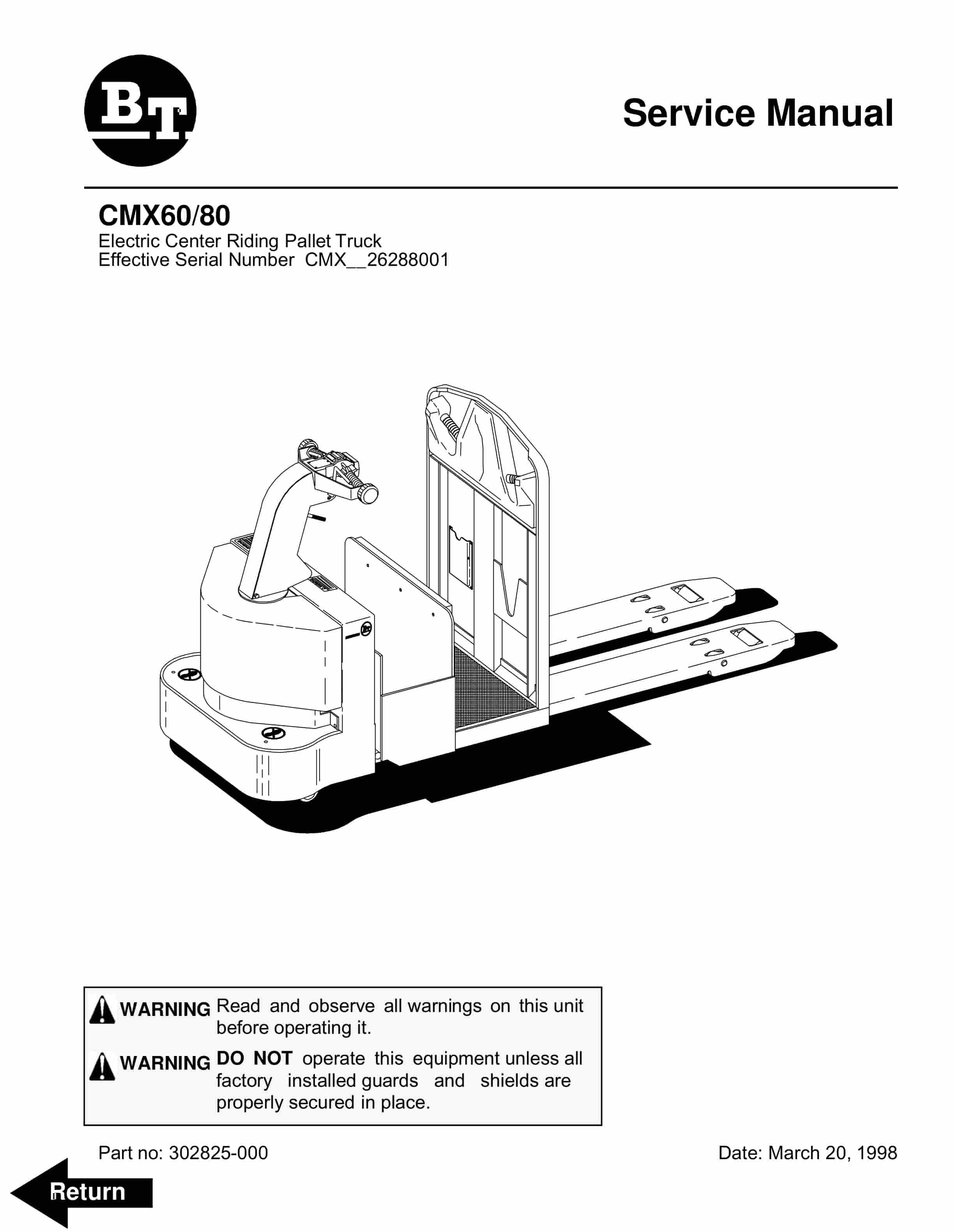
BT CMX-65, CMX-80 Center Control Riding Pallet Truck Service Manual 302825-000
$30.00
BT Service Manual PDF
BT CMX60, CMX80 Electric Center Riding Pallet Truck Service Manual 302825-000
$30.00
$30.00
BT Service Manual PDF
BT CMX-65, CMX-80 Center Control Riding Pallet Truck Service Manual 302825-000
BT Service Manual PDF
BT CMX60, CMX80 Electric Center Riding Pallet Truck Service Manual 302825-000