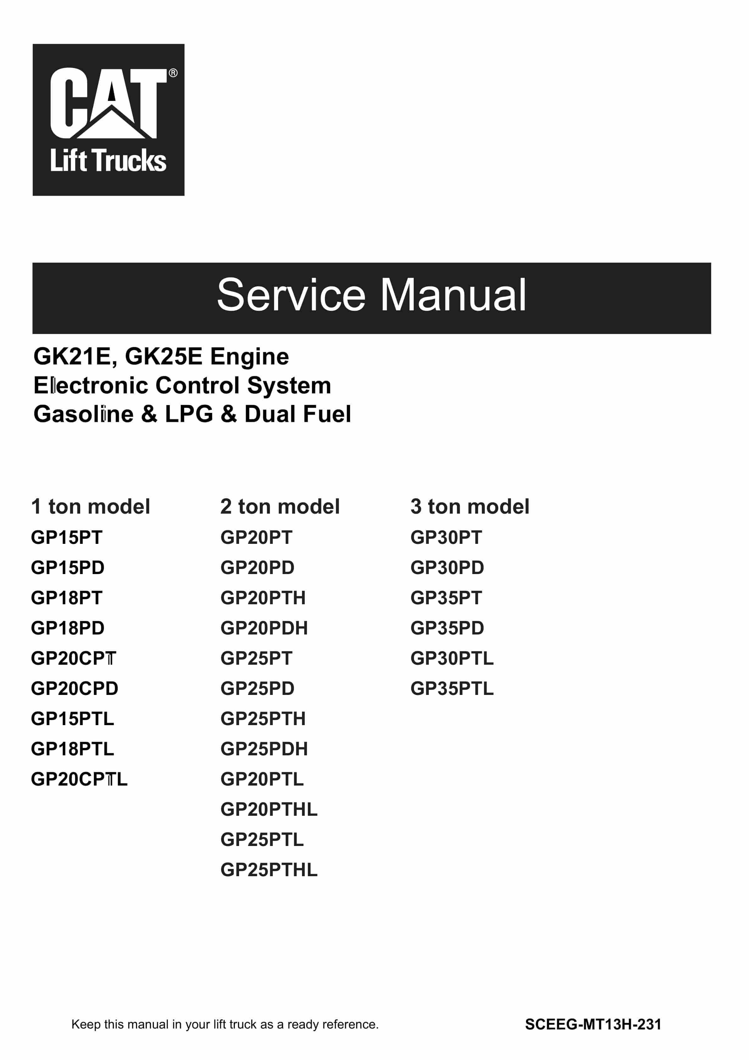
Caterpillar GK21E, GK25E Engine Electronic Control System Gasoline – LPG – Dual Fuel Service Manual SCEEG-MT13H-231
$50.00
- Type Of Manual: Service Manual
- Manual ID: SCEEG-MT13H-231
- Number of Pages: 180
- Size: 9.6MB
- Format: PDF
-
Model List:
- GK21E, GK25E
- 1. _COVER
- 2. _FOREWORD
- 2.1. HOW TO USE THIS MANUAL
- 2.1.1. Overview
- 2.1.2. Definition of Terms
- 2.1.3. Abbreviations and Standards
- 2.1.4. Definition of Units
- 2.1.5. Description
- 2.2. PRECAUTIONS FOR SAFETY AND QUALITY
- 2.2.1. Safe Operation
- 2.2.2. Correct Operation
- 2.2.3. Precautions for Radio Equipment Installation
- 2.2.4. Prohibition of Tamper
- 2.3. PRECAUTIONS
- 2.3.1. Precautions for Draining Engine Coolant
- 2.3.2. Precautions for Disconnecting Fuel Piping
- 2.3.3. Precautions for Removing and Disassembling
- 2.3.4. Precautions for Inspection, Correction, and Replacement
- 2.3.5. Precautions for Assembly and Installation
- 2.3.6. Precaution for Angle Wrench to Tightening Cylinder Head Bolts
- 2.3.7. Precautions for Using Power Tools
- 2.3.8. Precautions for Liquid Gasket Application
- 2.4. SPECIAL SERVICE TOOL
- 2.5. ENGINE OUT SIDE DRAWING
- 2.6. MAIN SPECIFICATION DATA
- 2.6.1. Main Specifications
- 2.6.2. Ignition System
- 2.6.3. Engine Fuel System and Engine Speed Control System
- 2.7. STAMPED LOCATION OF ENGINE NO.
- 2.8. ENGINE MAINTENANCE
- 2.8.1. Specifications
- 2.8.2. Maintenance Schedule
- 2.8.3. Oils and Capacity
- 2.8.4. Engine Inspection and Servicing
- 2.9. TIGHTENING TORQUE
- 2.9.1. Standard Bolt Tightening Torque
- 2.9.2. Tightening Torque for Engine Parts
- 2.10. TROUBLESHOOTING
- 2.11. ADJUSTMENT VALUE
- 2.12. ENGINE REMOVAL AND INSTALLATION
- 2.12.1. Removal of the Engine
- 2.12.2. Installation of the Engine
- 2.12.3. Inspection of the Engine
- 2.13. ENGINE SERVICE
- 2.13.1. Engine Disassembly
- 2.13.2. Inspection and Adjustment
- 2.13.3. Engine Assembly
- 2.14. ENGINE LUBRICATION SYSTEM
- 2.14.1. Lubrication system diagram
- 2.14.2. Specifications
- 2.14.3. Hydraulic Pressure
- 2.14.4. Tightening Torque
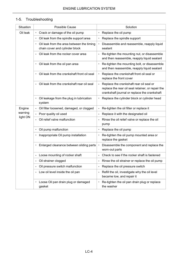
- 2.14.5. Troubleshooting
- 2.15. ENGINE COOLING SYSTEM
- 2.15.1. Cooling System Diagram
- 2.15.2. Specifications
- 2.15.3. Adjustment Value
- 2.15.4. Tightening torque
- 2.15.5. Troubleshooting
- 2.15.6. Cooling System Schematic
- 2.15.7. Water pump
- 2.15.8. Thermostat
- 2.15.9. Filling LLC into the Cooling System
- 2.16. TROUBLESHOOTING
- 2.17. ELECTRONIC CONTROLLED SYSTEM
- 2.17.1. System diagram for gasoline use
- 2.17.2. System diagram for LPG use
- 2.17.3. System diagram for gasoline and LPG combined use
- 2.18. REMOVAL AND INSTALLATION OF THE THROTTLE CHAMBER
- 2.18.1. Removal of the Throttle Chamber
- 2.18.2. Installing the Throttle Chamber
- 2.19. REMOVAL AND INSTALLATION OF GASOLINE FUEL INJECTOR
- 2.19.1. Auxiliary Work Preparation
- 2.19.2. Removal and Installation of the Fuel Hose
- 2.19.3. Removal and Installation of the Fuel Tube and Fuel Injector
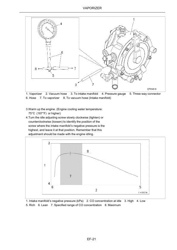
- 2.20. VAPORIZER
- 2.20.1. Description
- 2.20.2. Primary (Decompression) Chamber
- 2.20.3. Secondary Valve Room
- 2.20.4. Removal and Installation
- 2.20.5. Disassembly, Assembly, And Inspection
- 2.21. BLOWBY GAS RECIRCULATION DEVICE
- 2.21.1. System Diangram
- 2.21.2. Inspection of the Components
- 2.22. PRECAUTIONS FOR WORK
- 2.22.1. Engine Trouble Diagnosis
- 2.22.2. General Caution for Maintenance Work
- 2.23. ELECTRONIC CONTROLLED SYSTEM
- 2.23.1. Overview
- 2.23.2. Electronic Controlled System
- 2.23.3. Sensor and Actuator Control Items
- 2.24. TROUBLE DIAGNOSIS
- 2.24.1. ECU Component Parts Location
- 2.24.2. Circuit Diagram
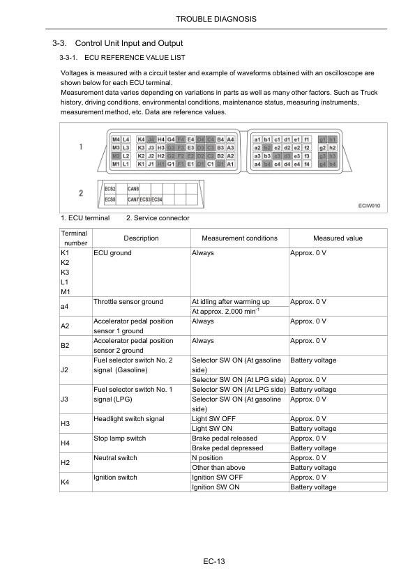
- 2.24.3. Control Unit Input and Output
- 2.24.4. Engine wiring reference value list
- 2.24.5. How to Proceed with Trouble Diagnosis
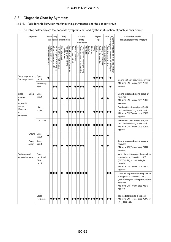
- 2.24.6. Diagnosis Chart by Symptom
- 2.24.7. Fail-safe function
- 2.24.8. DTC List
- 2.24.9. Service Tool
- 2.24.10. Active Test Support
- 2.25. BASIC INSPECTION
- 2.25.1. Inspection of Idle Speed
- 2.25.2. Inspection of the Ignition Timing
- 2.25.3. Throttle Learning Clear
- 2.25.4. Fuel Pressure Removal
- 2.26. COMPONENT PART INSPECTION
- 2.26.1. Symbol for Harness Connector
- 2.26.2. Crank angle Sensor
- 2.26.3. Cam angle sensor
- 2.26.4. Intake Pressure Temperature Sensor
- 2.26.5. Engine Coolant Temperature Sensor
- 2.26.6. Throttle Position Sensors 1 and 2
- 2.26.7. Accelerator Pedal Position Sensors 1 and 2
- 2.26.8. Stop Lamp Switch
- 2.26.9. Spark plug
- 2.26.10. Ignition coil
- 2.26.11. Gasoline injector
- 2.26.12. Fuel Pump
- 2.26.13. Throttle Control Motor
- 2.26.14. LPG shutoff valve
- 2.27. ENGINE CONTROL SYSTEM COMPONENTS
- 2.27.1. Removal and Installation
- 2.28. TROUBLESHOOTING
- 2.29. STARTER MOTOR (Dry Type)
- 2.29.1. Specifications
- 2.29.2. Components Diagram
- 2.29.3. Tightening Torque
- 2.30. ALTERNATOR
- 2.30.1. Inspection Before Removing the Alternator
- 2.30.2. Removal of the Alternator
- 3. _RR END
Caterpillar Service Manual PDF
Caterpillar Service Manual PDF
Caterpillar 1204F Diesel Engine Troubleshooting Service Manual 99799-67104
Caterpillar Service Manual PDF
Caterpillar 4G15, 4G63, 4G64, 6G72 Engine Service Manual 99719-34130
Caterpillar Service Manual PDF
Caterpillar 1204E Diesel Engine Service Manual SCEEA-AT15E-200
Caterpillar Service Manual PDF
Caterpillar 5M15D to 5M35D Mast Supplement Service Manual 99739-351T0
Caterpillar Service Manual PDF
Caterpillar 4G63, 4G64 Fuel System Supplement Service Manual 99729-85110
Caterpillar Service Manual PDF
Caterpillar 1204F Diesel Engine Systems Operation Testing and Adjusting Service Manual 99799-67103
Caterpillar Service Manual PDF
Caterpillar 1204F Diesel Engine Operation and Maintenance Manual Service Manual 99799-67105
Caterpillar Service Manual PDF
Caterpillar 1204E Diesel Engine Operation and Maintenance Manual Service Manual 99799-64105
