BT REFLEX RR B-E, RR B-E CC Service Manual 232808-040
$30.00
- Type Of Manual: Service Manual
- Manual ID: 232808-040
- : Service Manual PDF
- Number of Pages: 482
- Size: 16.0MB
- Format: PDF
Category: BT Service Manual PDF
-
Model List:
- REFLEX RR B-E, RR B-E CC
- 1. Contents
- 2. Technical data – M4
- 2.1. General tightening torque
- 2.1.1. Galvanised, non-oiled bolts
- 2.1.2. Untreated, oiled bolts
- 3. Introduction, maintenance – P1
- 3.1. Safety regulations during maintenance work
- 3.2. Cleaning and washing
- 3.2.1. Cleaning the exterior
- 3.2.2. Cleaning the motor compartment
- 3.2.3. Electrical components
- 3.3. Safe lifting
- 3.4. Opening motor compartment
- 3.4.1. RR B 1-8
- 3.5. Cab tilting
- 3.5.1. RR E 1-8
- 3.5.2. RR E 2-8 CC
- 4. Preventive maintenance – P2
- 4.1. Maintenance Schedule
- 4.1.1. RR B/E 1-8
- 4.1.2. RR B/E 2-8 CC
- 5. Oil and grease specification – P3
- 6. Tools – P4
- 6.1. Super Seal connector
- 6.1.1. AMP connector
- 6.1.2. AMP microtimer
- 6.1.3. Diverse tools
- 7. Cab heating/ventilation – 0630
- 7.1. General
- 7.2. Air conditioning unit
- 7.2.1. Ventilation
- 7.2.2. Main heater
- 7.2.3. Auxiliary heater
- 7.2.4. Temperature
- 7.2.5. Air direction
- 7.2.6. Fuses
- 7.2.7. Air filter
- 7.2.8. Emergency exit (12)
- 7.2.9. Lighting
- 8. Driver protection – 0840
- 8.1. General
- 8.2. Tilt Stops
- 8.2.1. Inspection and Adjustment
- 8.2.2. Removing the tilt stops
- 9. Electric pump motor -1710
- 9.1. General
- 9.2. Dismantling the pump motor
- 9.3. Dismantling and assembling the pump motor
- 9.3.1. Dismantling
- 9.3.2. Assembling
- 9.4. Bearing replacement
- 9.4.1. Dismantling
- 9.4.2. Assembling
- 9.5. Installation instructions for external temperature sensor
- 10. Electric steering motor – 1730
- 10.1. General
- 10.2. Replacing the steering motor
- 10.2.1. Dismantling
- 10.2.2. Assembling
- 10.3. Dismantling and assembling the carbon brushes
- 11. Electric drive motor – 1760
- 11.1. General
- 11.2. Dismantling the drive motor
- 11.3. Dismantling and assembling the drive motor
- 11.3.1. Dismantling the drive motor
- 11.3.2. Assembling the drive motor
- 11.4. Bearing replacement
- 11.4.1. Dismantling
- 11.4.2. N-side
- 11.4.3. Assembling
- 11.5. Installation instructions for external temperature sensor
- 12. Mechanical drive gear unit – 2550
- 12.1. General
- 12.2. Components/data for the drive assembly/transmission
- 12.2.1. Component placement
- 12.2.2. Technical data
- 12.2.3. Dismantling the transmission
- 12.3. Replacing the drive motor/drive transmission
- 12.3.1. Dismantling the drive motor
- 12.3.2. Dismantling the gear wheel
- 12.3.3. Dismantling the drive transmission
- 12.3.4. Assembling the transmission
- 12.3.5. Installing the drive motor
- 12.3.6. Assembling the gear wheel
- 12.4. Checking/replacing the oil
- 12.4.1. Checking/refilling the oil
- 12.4.2. Changing the Oil
- 12.5. Repairs
- 12.5.1. Replacing the drive shaft sealing ring
- 12.5.2. Leakage from the upper cover
- 12.5.3. Leakage from the lower cover
- 12.5.4. Replacing wheel bolts
- 13. Travel brake system – 3100.1
- 13.1. Without support arm brakes
- 13.2. General
- 13.3. Operating description
- 13.3.1. Releasing the accelerator
- 13.3.2. Travel direction selector
- 13.3.3. Pressing down the brake pedal
- 13.3.4. Parking brake
- 13.3.5. Emergency brake
- 13.4. Electromechanical disc brake, drive motor
- 13.5. Disassembly
- 13.6. Inspection
- 13.7. Assembly
- 13.8. Maintenance
- 13.8.1. Adjusting the play
- 13.8.2. Wear
- 13.8.3. Checking the braking force
- 14. Travel brake system – 3100.2
- 14.1. With support arm brake
- 14.2. General
- 14.3. Operating description
- 14.3.1. Releasing the accelerator
- 14.3.2. Travel direction selector
- 14.3.3. Pressing down the brake pedal
- 14.3.4. Parking brake
- 14.3.5. Emergency braking
- 14.4. Electromechanical disc brake, drive motor
- 14.5. Removal
- 14.6. Inspection
- 14.7. Assembly
- 14.8. Maintenance
- 14.8.1. Adjusting the play
- 14.8.2. Wear
- 14.8.3. Checking the braking force
- 14.9. Multiple disc brake, support arm
- 14.9.1. Assembling
- 14.9.2. Dismantling
- 14.9.3. Inspection
- 14.9.4. Assembling
- 14.10. Maintenance
- 14.10.1. Adjusting the play
- 15. Drive wheel – 3530
- 15.1. General
- 15.2. Dismantling the drive wheel
- 15.3. Assembling the drive wheel
- 16. Fork/support arm wheel – 3550.1
- 16.1. General
- 16.2. Dismantling the wheel
- 16.3. Assembling the wheel
- 16.4. Dismantling/assembling the wheel bearings
- 16.4.1. mm wheel and 300 mm wheel without brakes
- 16.4.2. mm wheel with brake and 350 mm wheel
- 17. Fork/support arm wheel – 3550.2
- 17.1. Valid for T-code 403-404
- 17.2. General
- 17.3. Dismantling the wheel
- 17.4. Assembling the drive wheel
- 17.5. Dismantling the wheel bearings
- 17.6. Assembling the wheel bearings
- 18. Mechanical steering system – 4100
- 18.1. General
- 18.2. Replacing the steering generator
- 18.2.1. Dismantling
- 18.2.2. Assembling
- 19. Steering angle sensor – 4350
- 19.1. General
- 19.2. Procedure
- 19.2.1. Adjustment of the steering angle sensor
- 20. Electrical system – 5000
- 20.1. Electrical Panel
- 20.2. List of symbols and wiring diagrams
- 20.2.1. List of symbols
- 20.2.2. Wiring diagram
- 20.3. Component list
- 20.3.1. Figure 1
- 20.3.2. Figure 2
- 20.3.3. Figure 3
- 20.3.4. Figure 4
- 20.3.5. Figure 5
- 20.3.6. Figure 6
- 20.3.7. Figure 7
- 20.3.8. Figure 8
- 20.3.9. Figure 9
- 20.3.10. Figure 10
- 20.3.11. Figure 11
- 20.3.12. Figure 12
- 20.4. Functional description
- 20.4.1. Truck not started up
- 20.4.2. Truck started up
- 20.4.3. Selection of travel direction
- 20.4.4. Driving
- 20.4.5. Steering
- 20.4.6. Steering wheel indicator
- 20.4.7. Braking
- 20.4.8. Fork lift
- 20.4.9. Maximum height
- 20.4.10. Maximum height
- 20.4.11. Fork lowering
- 20.4.12. Mast out/in
- 20.4.13. Fork tilt up/down
- 20.4.14. Hydraulic function 4
- 20.4.15. Hydraulic function 5
- 20.4.16. Cab tilt
- 20.4.17. Height indication
- 20.4.18. Height pre-set
- 20.4.19. Weighing
- 20.4.20. Driver identification
- 21. Battery – 5110
- 21.1. Battery dimensions
- 21.2. Setting the battery parameters on RR trucks fitted with Hawker Evolution gel batteries
- 21.2.1. General
- 21.2.2. Battery recommendation
- 21.2.3. Battery installation
- 21.2.4. Recommended parameter setting for ventilation regulated batteries
- 21.2.5. Instructions for verifying the parameter setting
- 22. Transistor panel – 5460
- 22.1. Frequency converter
- 22.1.1. General description
- 22.1.2. Terminal connections and pole bolts
- 22.1.3. Technical data
- 22.1.4. Programming
- 23. Electronic card – 5710
- 23.1. General description
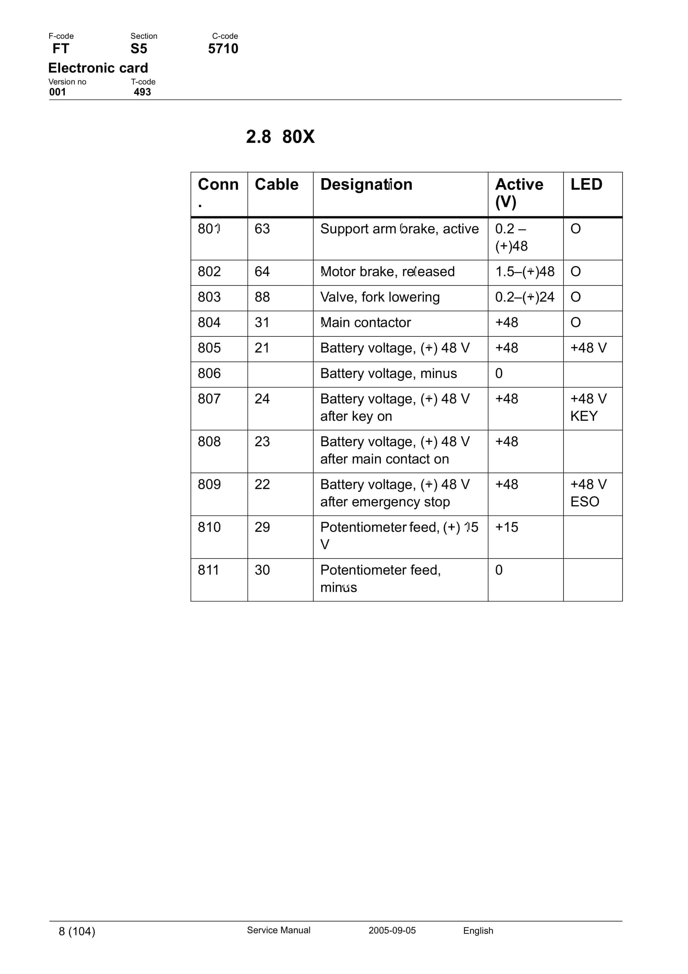
- 23.2. Terminal connections and voltages on A5
- 23.2.1.
- 23.2.2.
- 23.2.3.
- 23.2.4.
- 23.2.5.
- 23.2.6.
- 23.2.7.
- 23.2.8.
- 23.2.9.
- 23.3. Adjusting the lowering speed
- 23.4. Display and programming
- 23.4.1. Keyboard
- 23.5. Parameter settings for all parameters
- 23.5.1. Parameters
- 23.5.2. Parameter 1
- 23.5.3. Parameter 2
- 23.5.4. Parameter 3
- 23.5.5. Parameter 4
- 23.5.6. Parameter 5
- 23.5.7. Parameters 6 and 7
- 23.5.8. Parameter 11
- 23.5.9. Parameter 12
- 23.5.10. Parameters 13 to 14
- 23.5.11. Parameters 15 and 16
- 23.5.12. Parameters 17 and 18
- 23.5.13. Parameter 19
- 23.5.14. Parameter 20
- 23.5.15. Parameter 21
- 23.5.16. Parameter 22
- 23.5.17. Parameter 23
- 23.5.18. Parameter 24
- 23.5.19. Parameter 25
- 23.5.20. Parameter 26
- 23.5.21. Parameter 27
- 23.5.22. Parameter 28
- 23.5.23. Parameter 29
- 23.5.24. Parameter 30
- 23.5.25. Parameter 31
- 23.5.26. Parameter 37
- 23.5.27. Parameter 38
- 23.5.28. Parameter 39
- 23.5.29. Parameters 40 to 42
- 23.5.30. Other parameters
- 23.6. Operating Time
- 23.6.1. Installing a new card in the truck.
- 23.7. Warning Codes
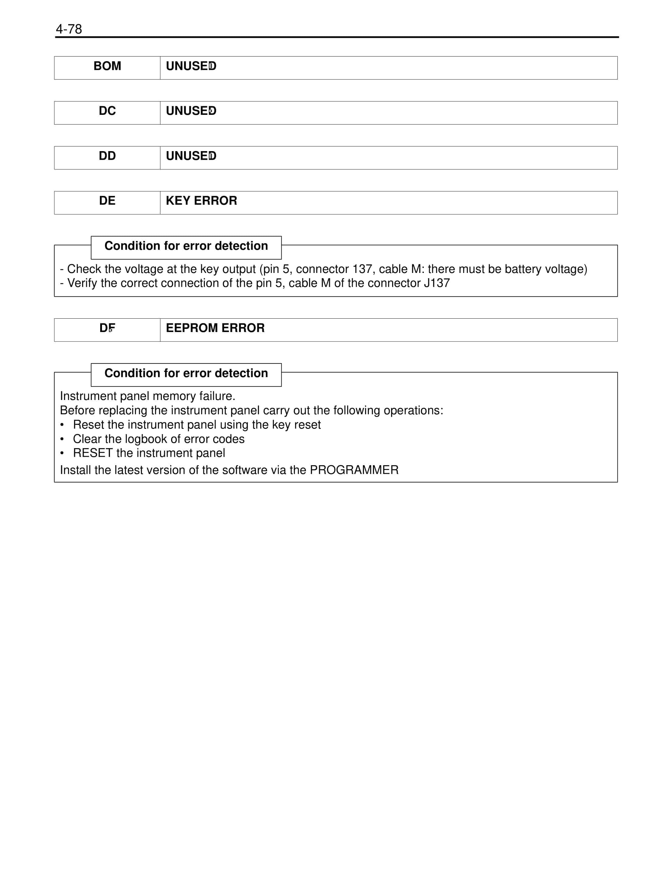
- 23.8. Error codes
- 23.8.1. Error mode
- 23.8.2. Safety logic
- 23.9. Warning codes without registration
- 23.10. Warning codes with registration
- 23.11. Error codes
- 23.11.1. Error codes with registration
- 24. Keyboard
- 24.1. General
- 24.2. Display
- 24.2.1. Description of the keyboard symbols
- 24.3. Function
- 24.3.1. Function 0
- 24.3.2. Function 1
- 24.3.3. Function 2
- 24.3.4. Function 3
- 24.4. Programming
- 24.4.1. LED status.
- 24.4.2. Driver codes
- 25. Hydraulics – 6000
- 25.1. General
- 25.2. Symbols
- 25.2.1. Hydraulics diagram 1 (4)
- 25.2.2. Hydraulics diagram 2 (4)
- 25.2.3. Hydraulics diagram 3 (4)
- 25.2.4. Hydraulics diagram 4 (4)
- 25.3. List of symbols
- 25.3.1. Component placement 1 (3)
- 25.3.2. Component placement 2 (3)
- 25.3.3. Component placement 3 (3)
- 25.4. Adjusting fork lowering
- 25.5. Adjusting the maximum lifting capacity
- 26. Hydraulic pump – 6140
- 26.1. General
- 26.2. Replacing the hydraulic pump
- 26.2.1. Dismantling
- 26.2.2. Assembling
- 27. Hydraulic connections – 6230
- 27.1. General
- 27.2. Tightening torque for hydraulic connections
- 27.2.1. Conical connection with O-ring
- 27.2.2. Tredo seal
- 27.2.3. Pipe coupling
- 27.2.4. Connection screwed into aluminium
- 27.2.5. Connection screwed into steel
- 28. Mast mounted hose reel – 6370
- 28.1. General
- 28.2. Assembling
- 28.3. Check after assembly
- 29. Main lift cylinder – 6610
- 29.1. General
- 29.2. Tools
- 29.3. Dismantling the lift cylinders from the mast
- 29.4. Dismantling the cylinder
- 29.4.1. Dismantling the rod seal, guide ring, guide ring holder and locking ring in lift cylinder
- 29.4.2. Fit the locking ring, rod seal, guide ring and guide ring holder in the lift cylinder
- 29.4.3. Dismantling and assembling the hose rupture valve
- 29.5. Assembling the cylinder
- 29.5.1. Assembling the cylinder in the mast
- 30. Free lift cylinder – 6620
- 30.1. General
- 30.2. Tools
- 30.3. Dismantling
- 30.3.1. Dismantling the cylinder
- 30.4. Dismantle the rod seal and support ring
- 30.4.1. Assembling the rod seal and support ring
- 30.5. Dismantling the piston
- 30.5.1. Fitting the piston in the free lift cylinder
- 30.6. Dismantling and assembling the hose rupture valve
- 30.7. Assembling the cylinder
- 30.8. Assembly
- 31. Reach cylinder – 6650
- 31.1. General
- 31.2. Assembling and dismantling the reach cylinder
- 31.3. Dismantling
- 31.3.1. Dismantling the cylinder
- 31.3.2. Dismantle the rod seal and the support ring
- 31.3.3. Assembling the rod seal and the support ring
- 31.3.4. Dismantling the ram
- 31.3.5. Assembling the ram
- 31.3.6. Assembling the cylinder
- 31.4. Assembling
- 32. Tilt cylinder – 6660.1
- 32.1. General
- 32.2. Mast with valve on the fork carriage
- 32.2.1. Dismantling the fork carriage
- 32.2.2. Dismantling the cylinder
- 32.2.3. Dismantling the rod seal
- 32.2.4. Dismantling the ram
- 32.2.5. Assembling the ram
- 32.2.6. Assembling the rod seal
- 32.2.7. Assembling the cylinder
- 32.2.8. Assembling the fork carriage
- 32.3. Mast without valve on the fork carriage
- 32.3.1. Dismantling the fork carriage
- 32.3.2. Dismantling the cylinder
- 32.3.3. Dismantling the rod seal
- 32.3.4. Dismantling the ram
- 32.3.5. Assembling the ram
- 32.3.6. Assembling the rod seal
- 32.3.7. Assembling the cylinder
- 32.3.8. Assembling the fork carriage
- 33. Tilt cylinder – 6660.2
- 33.1. General
- 33.2. Dismantling the cylinder from the truck
- 33.3. Dismantling and assembling the cylinder
- 33.3.1. Dismantling the cylinder
- 33.3.2. Dismantle the seals and the support ring
- 33.3.3. Assembling the rod seal and the support ring
- 33.3.4. Dismantling the ram
- 33.3.5. Assembling the ram
- 33.3.6. Assembling the cylinder
- 33.4. Refitting the cylinder in the truck
- 34. Main mast -7100
- 34.1. General
- 34.2. List of tools
- 34.3. Transporting the truck
- 34.4. Assembling the mast
- 34.5. Dismantling the mast
- 34.6. Adjusting the play
- 34.6.1. Adjusting the mast play.
- 34.6.2. Radial play
- 34.7. Assembly
- 34.8. Problem with the mast rollers
- 34.9. Adjusting the distance between the forks and floor
- 35. Main lift chain system – 7120
- 35.1. General
- 35.2. Checking the chain setting
- 35.3. Chain inspection
- 35.3.1. Noise
- 35.3.2. Surface rust
- 35.3.3. Rusty links
- 35.3.4. Stiff links
- 35.3.5. Bolt rotation
- 35.3.6. Loose bolts
- 35.3.7. Outline wear
- 35.3.8. Stretching
- 35.3.9. Damage
- 35.3.10. Damaged discs
- 35.3.11. Damaged bolts
- 35.3.12. Dirty chain
- 35.4. Cleaning
- 35.5. Lubrication
- 36. Lifting devices – 7400
- 36.1. General
- 36.1.1. Inspection intervals
- 36.1.2. Inspection
- 36.1.3. Surface cracks
- 36.1.4. Difference in height between the fork tips
Rate this product
You may also like
BT Service Manual PDF
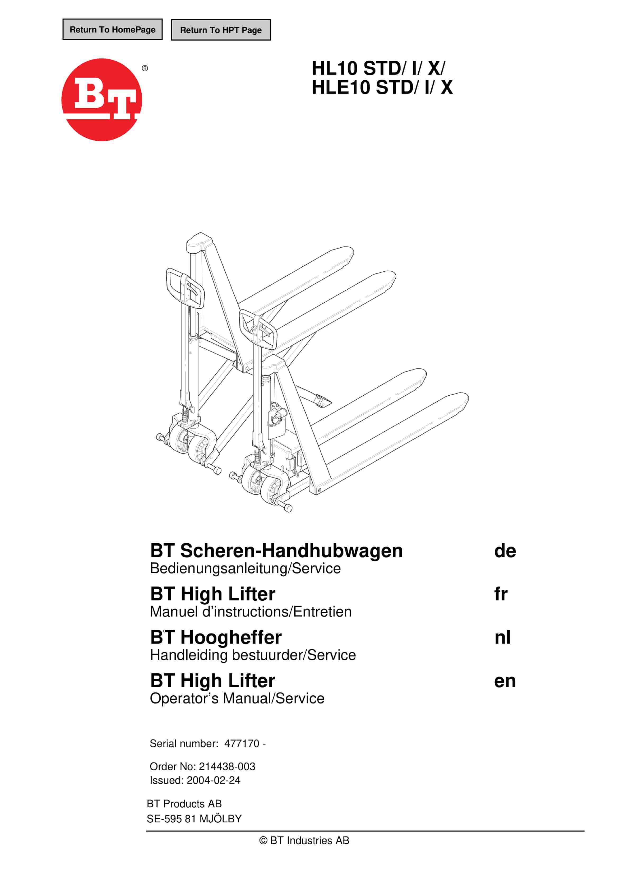
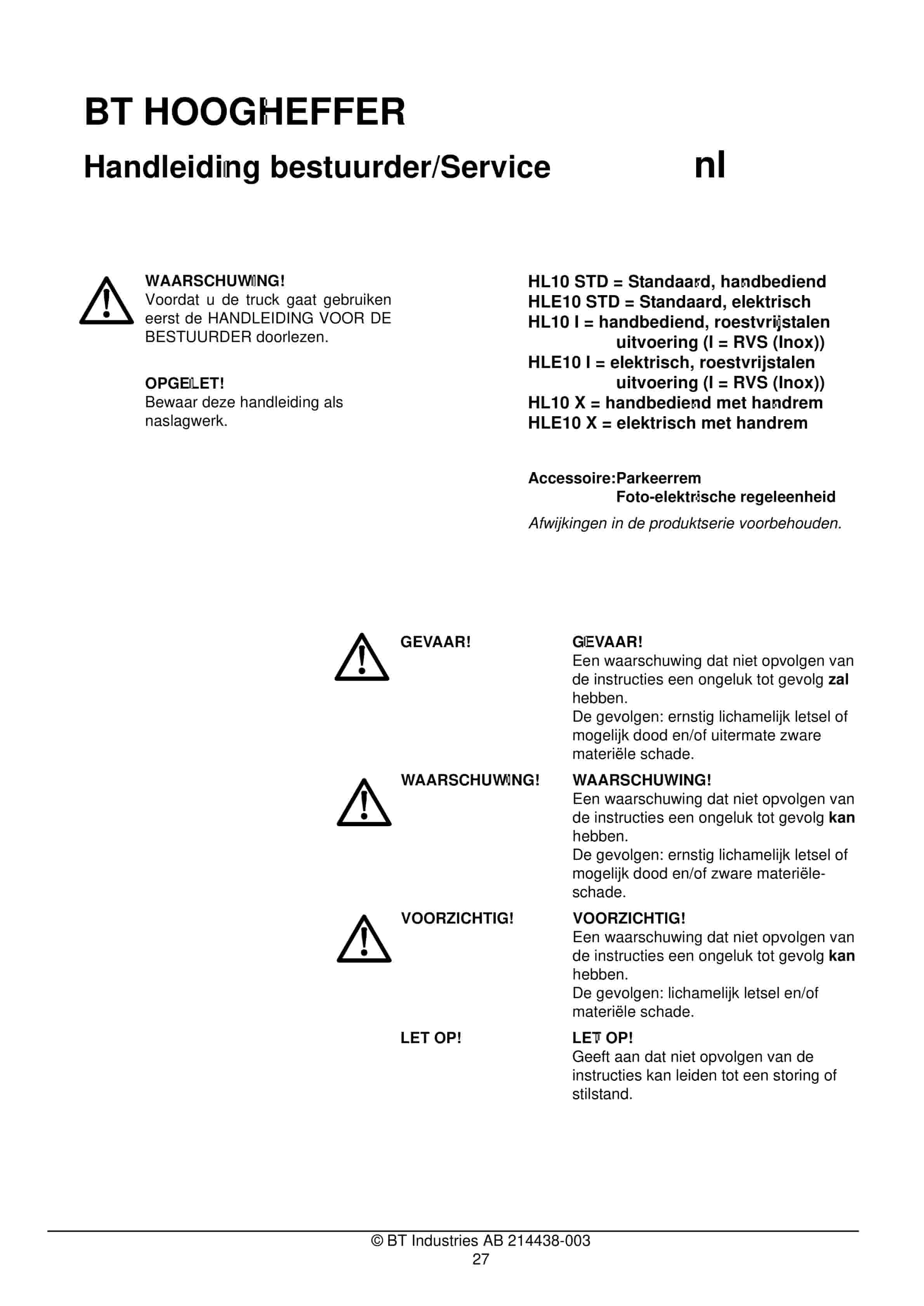
BT HL10 STD, HL10 I, HL10 X, HLE10 STD, HLE10 I, HLE10 X Operator And Service Manual 214438-003
$30.00
BT Service Manual PDF
$30.00
BT Service Manual PDF
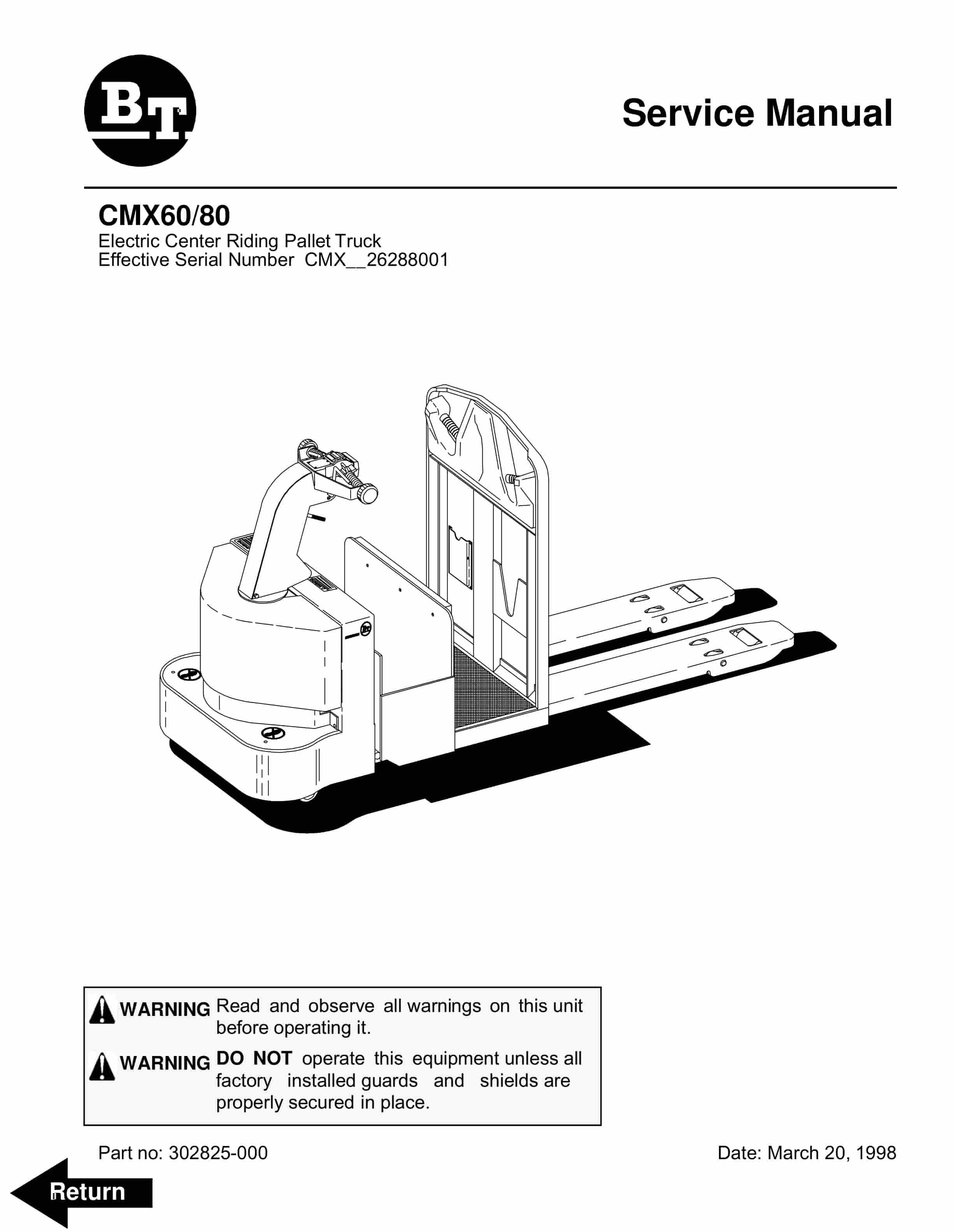
BT CMX60, CMX80 Electric Center Riding Pallet Truck Service Manual 302825-000
$30.00