


Caterpillar Operator Manual PDF
Caterpillar CL115 Compact Loader Operation And Maintenance Manual A6474X384
Caterpillar Operator Manual PDF
Caterpillar CM345-N Continuous Miner Operation And Maintenance Manual BI001590
Caterpillar Operator Manual PDF
Caterpillar BUC-SCR 120 Series Battery Charger Operation And Maintenance Manual BI001952
Caterpillar Operator Manual PDF
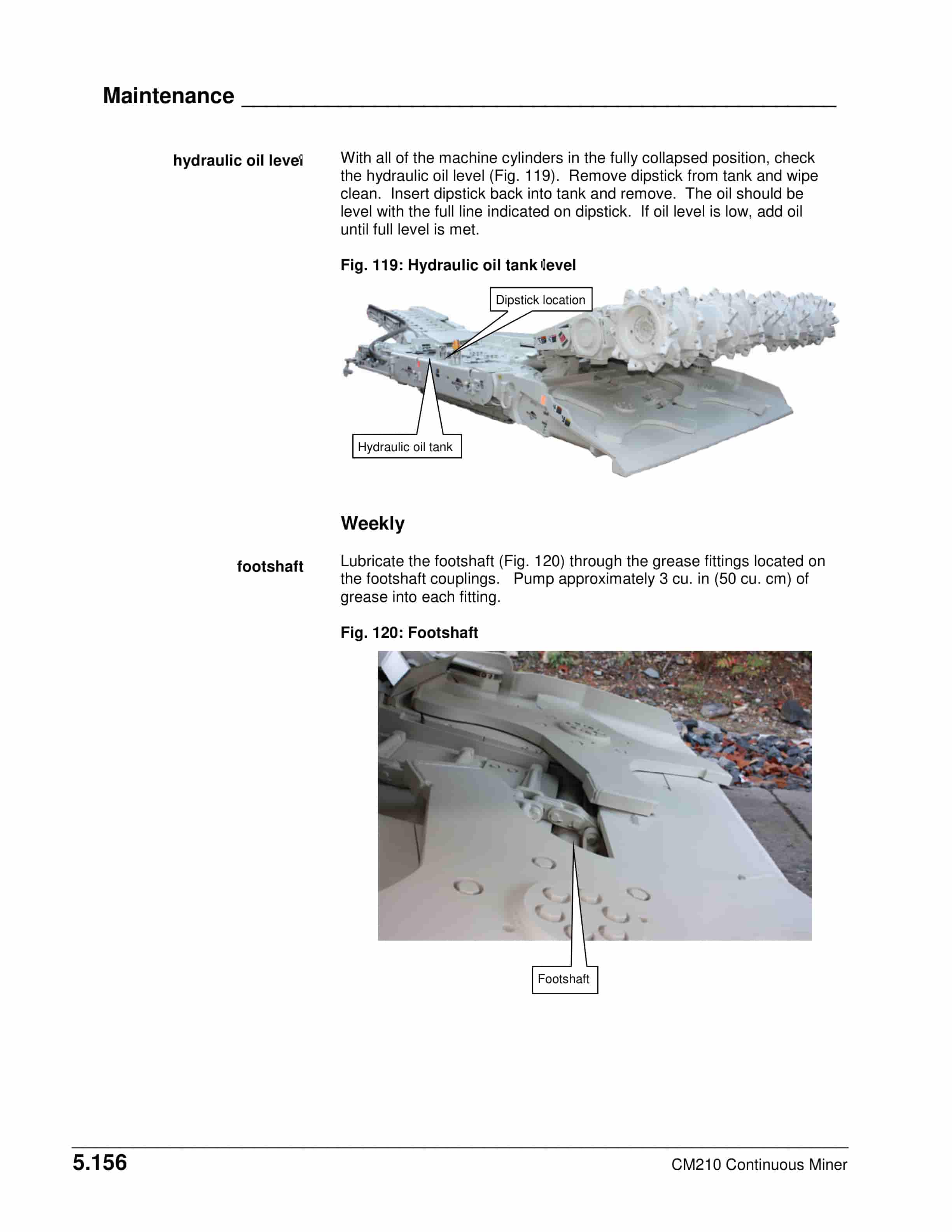
Caterpillar CM210 Continuous Miner Operation And Maintenance Manual A6474X350
Caterpillar Operator Manual PDF
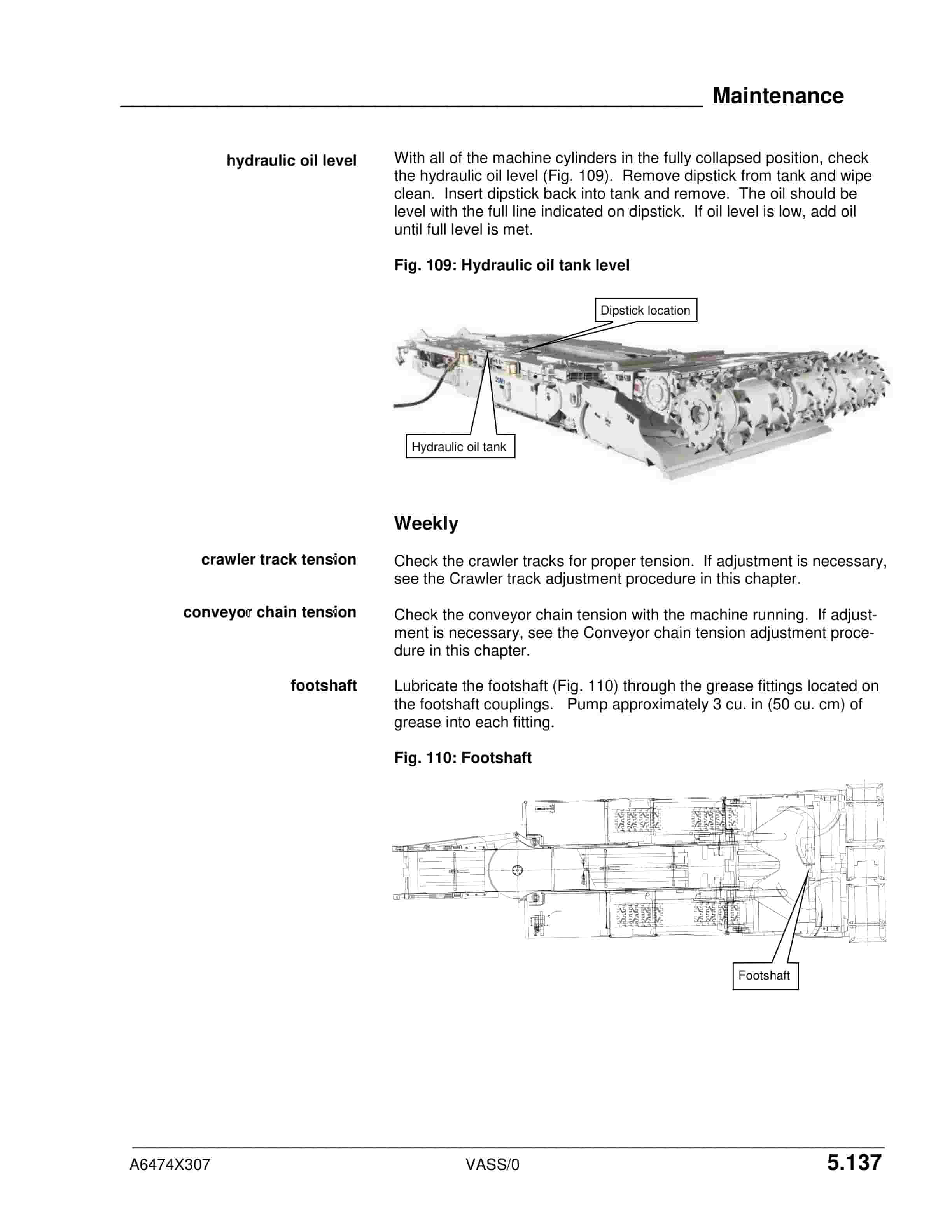
Caterpillar CM220 Continuous Miner Operation And Maintenance Manual A6474X307
Caterpillar Operator Manual PDF
Caterpillar CM345 Continuous Miner Operation And Maintenance Manual BI001592-02
Caterpillar Operator Manual PDF
Caterpillar CM340 Continuous Miner Operation And Maintenance Manual BI001585-01
Caterpillar Operator Manual PDF
Caterpillar CM445 Continuous Miner Operation And Maintenance Manual A6474X368

Caterpillar Operator Manual PDF
Caterpillar CM345 Continuous Miner Operation And Maintenance Manual BI001589
Caterpillar Operator Manual PDF
Caterpillar CM340 Continuous Miner Operation And Maintenance Manual BI001584-01