


BT VR Service Manual 174803-040
$30.00
- Type Of Manual: Service Manual
- Manual ID: 174803-040
- : Service Manual PDF
- Number of Pages: 446
- Size: 17.6MB
- Format: PDF
Category: BT Service Manual PDF
-
Model List:
- VR
- 1. Contents
- 2. General product information – M2
- 2.1. Presentation of BTs narrow aisle trucks
- 2.2. Application areas for BTs narrow aisle trucks
- 2.3. Prohibited applications for BTs narrow aisle trucks
- 2.4. Truck data
- 2.5. Truck dimensions
- 2.6. Identification plate, truck
- 2.7. Capacity plate
- 2.8. Modification plate
- 2.9. Identification plate, mast
- 2.10. Main components
- 2.11. Warning and information plates and symbols
- 3. Technical data – M4
- 4. Introduction and safety, maintenance – P1
- 4.1. Safety regulations with maintenance work
- 4.1.1. Tilting the cab up on cold store trucks
- 4.1.2. Tilting the cab down on cold store trucks
- 4.2. Cleaning and washing
- 4.2.1. External cleaning
- 4.2.2. Cleaning the motor compartment
- 4.2.3. Electrical components
- 4.3. Safe lifting
- 5. Preventive maintenance – P2
- 5.1. Maintenance Schedule
- 6. Oil and grease specification – P3
- 7. Tools – P4
- 7.1. Electrical contacts
- 7.1.1. Super Seal contacts
- 7.1.2. AMP contacts
- 7.2. Miscellaneous tools
- 8. Chassis – 0000
- 8.1. General
- 8.2. List of tools
- 8.3. Transporting the truck
- 8.4. Assembling the mast
- 8.5. Installation in narrow aisles
- 8.5.1. General
- 8.5.2. Track-guided truck
- 8.5.3. Wire guided truck
- 8.5.4. General adjustment
- 9. Frame, mounted components – 0400
- 9.1. General tightening torque
- 9.1.1. Galvanised, non oiled bolts
- 9.1.2. Untreated, oiled bolts
- 10. Driver Protection – 0840
- 10.1. General
- 10.2. Tilt Stops
- 11. Electric Pump Motor – 1710
- 11.1. General
- 11.2. Dismantling the Pump Motor
- 11.3. Removing and Replacing the Pump Motor
- 11.3.1. Dismantling
- 11.3.2. Assembling
- 11.4. Bearing Replacement
- 11.4.1. Dismantling
- 11.4.2. Re-Assembly
- 11.5. Installation Instructions for External Temperature Sensor
- 12. Electric Steering Motor – 1730
- 12.1. General
- 12.2. Replacing the Steering Motor
- 12.2.1. Dismantling
- 12.2.2. Re-Assembly
- 12.3. Removing and Replacing the Carbon Brushes
- 13. Electric Drive Motor – 1760
- 13.1. General
- 13.2. Dismantling the Drive Motor
- 13.3. Dismantling and Assembling the Drive Motor
- 13.3.1. Removing the gear wheel
- 13.3.2. Removing the brakes
- 13.3.3. Assembling the Drive Motor
- 13.4. Bearing Replacement
- 13.4.1. Dismantling
- 13.4.2. Assembling
- 13.5. Installation Instructions for External Temperature Sensor
- 14. Mechanical Drive Gear Unit
- 14.1. General
- 14.2. Drive/Transmission Assemblys Main Components and Technical Data
- 14.2.1. Position of Components
- 14.2.2. Technical data
- 14.2.3. Dismantling the Transmission
- 14.3. Replacing the Drive Motor/Drive Transmission
- 14.3.1. Dismantling the Drive Motor
- 14.3.2. Removal of the Drive Transmission
- 14.3.3. Assembling the Drive Transmission
- 14.3.4. Installing the Drive Motor
- 14.4. Checking/Replacing the Oil
- 14.4.1. Changing the Oil
- 14.5. Repairs
- 14.5.1. Dismantling
- 14.5.2. Re-Assembly
- 14.5.3. Leakage from the Upper Cover
- 14.5.4. Leakage from the Lower Cover
- 14.5.5. Replacing Wheel Bolts
- 15. Travel brake system – 3100
- 15.1. Brake system
- 15.1.1. General
- 15.2. Description of function
- 15.2.1. Releasing the accelerator
- 15.2.2. Changing travel direction
- 15.2.3. Pressing the brake pedal (without support arm brake)
- 15.2.4. Pressing the brake pedal (with support arm brakes)
- 15.2.5. Parking brake
- 15.2.6. Emergency braking
- 15.3. Electromechanical disc brake, drive motor
- 15.3.1. Assembling
- 15.3.2. Dismantling
- 15.3.3. Maintenance
- 15.4. Multiple disc brake, support arm
- 15.4.1. Assembly
- 15.4.2. Dismantling
- 15.4.3. Maintenance
- 16. Drive wheel – 3530
- 16.1. General
- 16.2. Dismantling the drive wheel
- 16.3. Assembling the drive wheel
- 17. Fork/support arm wheel – 3550
- 17.1. General
- 17.2. Dismantling the wheel
- 17.3. Assembling the wheel
- 17.4. Dismantling/assembling the wheel bearings
- 17.4.1. Dismantling the bearing
- 17.4.2. Assembling the bearing
- 18. Electric steering wheel/lever – 4310
- 18.1. General
- 18.2. Replacement of the steering generator
- 18.2.1. Dismantling
- 18.2.2. Assembly
- 19. Steering angle sensor – 4350
- 19.1. General
- 19.2. Adjustment of directional sensor
- 19.3. Adjustment of the steering angle sensor
- 20. Wire guidance – 4500
- 20.1. General
- 20.2. Generator
- 20.2.1. Technical data
- 20.3. Wire guidance system overview
- 20.4. Wire guidance components
- 20.4.1. Antennae, W1, W2
- 20.4.2. Control unit, A3
- 20.4.3. Home position sensor, S85
- 20.4.4. Steering angle sensor, U15
- 20.4.5. Diverse
- 20.5. Operating description
- 20.5.1. Run mode
- 20.5.2. Service mode
- 20.5.3. Parameter 36
- 20.5.4. Parameter 71
- 20.5.5. Parameter 72
- 20.5.6. Parameter 73
- 20.5.7. Parameter 74
- 20.5.8. Parameter 75
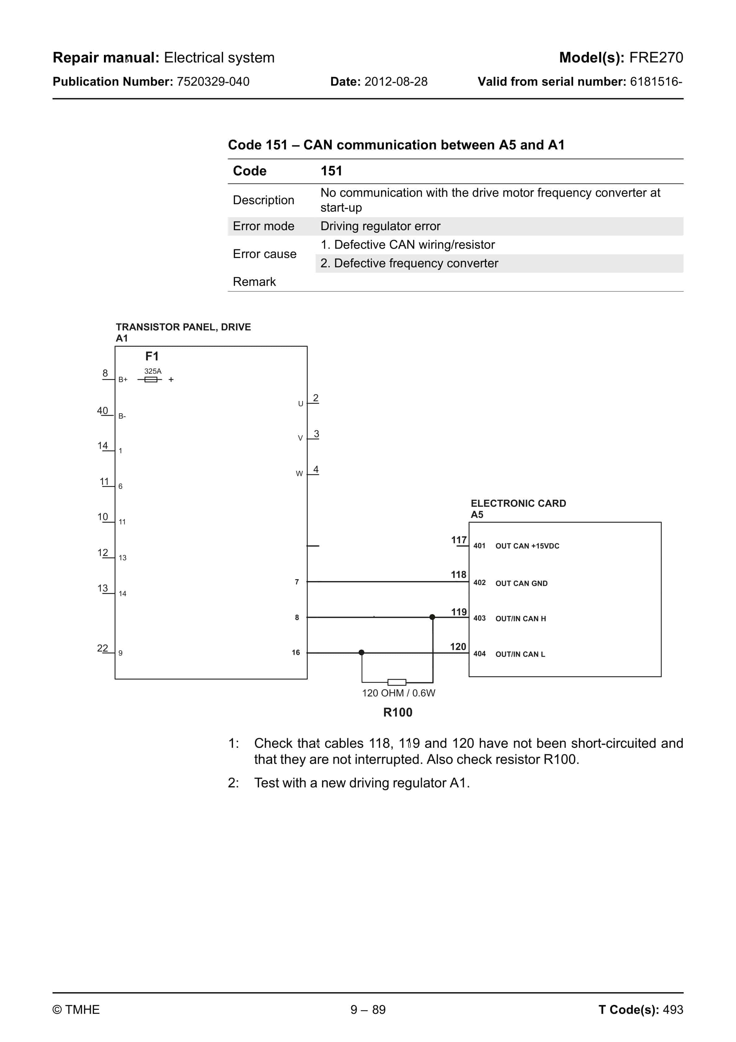
- 20.6. Error Codes
- 20.6.1. Error codes detected by electronic card A5
- 20.6.2. Error code detected by electronic card A3, WG-control unit
- 21. Electrical System – 5000
- 21.1. General
- 21.2. Electronics Card, traction controller A1 and lift controller A2
- 21.2.1. General
- 21.2.2. Terminal Connections and Pole Bolts
- 21.2.3. Technical Data
- 21.2.4. Installation of New Controller on Truck
- 21.2.5. Programming
- 21.3. Electronics Card, Fork unit, A4
- 21.3.1. General
- 21.3.2. Terminal Connections
- 21.3.3. Installation of New Card on Truck
- 21.3.4. Programming
- 21.4. Electronics Card, Main Card, A5
- 21.4.1. General
- 21.4.2. Terminal Connections and Voltages on A5
- 21.4.3. Installation of New Card on Truck
- 21.4.4. Programming
- 21.5. Electrical System, Overview
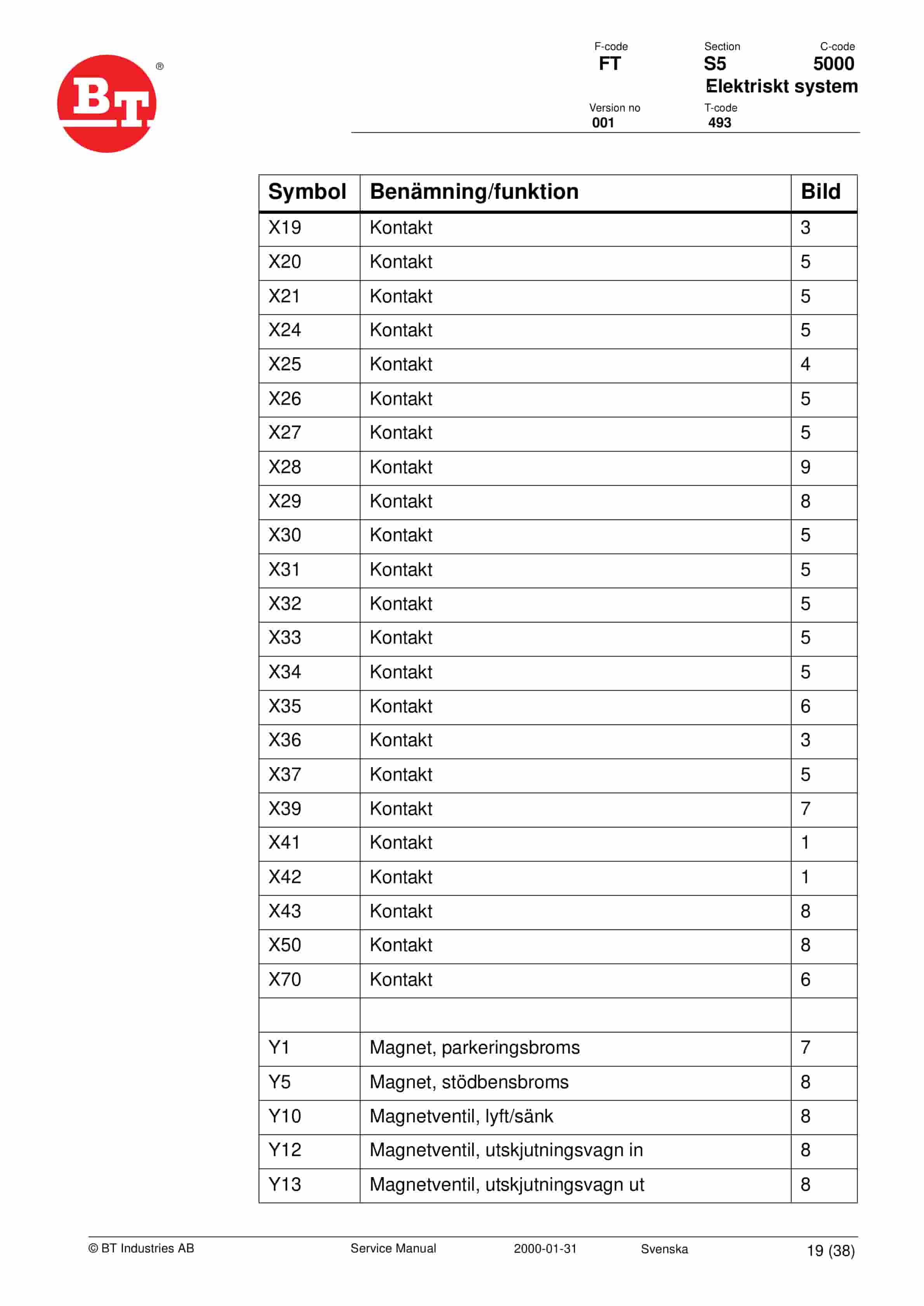
- 21.6. Symbol List and Wiring Diagrams
- 21.6.1. Symbol List
- 21.6.2. Wiring Diagram (1/25)
- 21.6.3. Wiring Diagram (2/25)
- 21.6.4. Wiring Diagram (3/25)
- 21.6.5. Wiring Diagram (4/25)
- 21.6.6. Wiring Diagram (5/25)
- 21.6.7. Wiring Diagram (6/25)
- 21.6.8. Wiring Diagram (7/25)
- 21.6.9. Wiring Diagram (8/25)
- 21.6.10. Wiring Diagram (9/25)
- 21.6.11. Wiring Diagram (10/25)
- 21.6.12. Wiring Diagram (11/25)
- 21.6.13. Wiring Diagram (12/25)
- 21.6.14. Wiring Diagram (13/25)
- 21.6.15. Wiring Diagram (14/25)
- 21.6.16. Wiring Diagram (15/25)
- 21.6.17. Wiring Diagram (16/25)
- 21.6.18. Wiring Diagram (17/25)
- 21.6.19. Wiring Diagram (18/25)
- 21.6.20. Wiring Diagram (19/25)
- 21.6.21. Wiring Diagram (20/25)
- 21.6.22. Wiring Diagram (21/25)
- 21.6.23. Wiring Diagram (22/25)
- 21.6.24. Wiring Diagram (23/25)
- 21.6.25. Wiring Diagram (24/25)
- 21.6.26. Wiring Diagram (25/25)
- 21.6.27. Component List, Standard Truck
- 21.6.28. Component identification
- 21.7. Functional Description
- 21.7.1. Key in Position 0
- 21.7.2. Key in Position I, Driver Seated
- 21.7.3. Direction of Travel Selection
- 21.7.4. Driving
- 21.7.5. Travel speeds
- 21.7.6. Steering
- 21.7.7. Braking
- 21.7.8. Aisle-End Slowdown
- 21.7.9. Fork Lifting
- 21.7.10. Height Indication
- 21.7.11. Lift height limit
- 21.7.12. Height Pre-Set
- 21.7.13. Fork Lowering
- 21.7.14. Lateral Movement/Traversing of Forks
- 21.7.15. Rotating the Forks
- 21.7.16. Simultaneous Traversing and Rotation Movement
- 21.7.17. Extra Hydraulic Functions
- 21.7.18. Weighing
- 21.7.19. Driver Identification
- 21.8. Parameter
- 21.8.1. Parameter Settings
- 21.8.2. Parameter 1
- 21.8.3. Parameter 2
- 21.8.4. Parameter 3
- 21.8.5. Parameter 4
- 21.8.6. Parameter 5
- 21.8.7. Parameter 6
- 21.8.8. Parameter 7
- 21.8.9. Parameter 8
- 21.8.10. Parameter 10
- 21.8.11. Parameter 11
- 21.8.12. Parameter 12
- 21.8.13. Parameter 13
- 21.8.14. Parameter 14
- 21.8.15. Parameter 15
- 21.8.16. Parameter 16
- 21.8.17. Parameters 17 and 18
- 21.8.18. Parameter 19
- 21.8.19. Parameter 20
- 21.8.20. Parameter 21
- 21.8.21. Parameter 22
- 21.8.22. Parameter 23
- 21.8.23. Parameter 24
- 21.8.24. Parameter 25
- 21.8.25. Parameter 26
- 21.8.26. Parameter 27
- 21.8.27. Parameter 28
- 21.8.28. Parameter 29
- 21.8.29. Parameter 36
- 21.8.30. Parameter 37
- 21.8.31. Parameter 38
- 21.8.32. Parameter 39
- 21.8.33. Parameters 40 to 42
- 21.8.34. Parameter 43
- 21.8.35. Parameter 44
- 21.8.36. Parameter 45
- 21.8.37. Parameter 46
- 21.8.38. Parameter 47
- 21.8.39. Parameter 48
- 21.8.40. Parameter 50
- 21.8.41. Parameter 51
- 21.8.42. Parameter 53
- 21.8.43. Parameter 54
- 21.8.44. Parameter 55
- 21.8.45. Parameter 56
- 21.8.46. Parameter 57
- 21.8.47. Parameter 58
- 21.8.48. Parameter 59
- 21.8.49. Parameter 60
- 21.8.50. Parameter 61
- 21.8.51. Parameter 62
- 21.8.52. Parameter 63
- 21.8.53. Parameter 64
- 21.8.54. Parameter 65
- 21.8.55. Parameter 66
- 21.8.56. Parameter 67
- 21.9. Instrument Panel and Display
- 21.9.1. Show
- 21.9.2. Operating Time
- 21.9.3. Programming
- 21.10. Codes
- 21.10.1. Warning Codes
- 21.10.2. Error mode
- 21.10.3. Safety Logic
- 21.10.4. Warning Codes without Registration
- 21.10.5. Warning Codes with Registration
- 21.10.6. Error Codes
- 21.10.7. Error Codes with Registration
- 22. Hydraulic system – 6000
- 22.1. General
- 22.2. Hydraulic schematics
- 22.2.1. Symbols
- 22.2.2. Hydraulic schematics
- 22.2.3. Component description
- 22.3. Hydraulic components, positioning
- 22.3.1. Overview
- 22.3.2. Hydraulic unit
- 22.3.3. Fork unit
- 22.3.4. Cab tilt function (cold store cab)
- 23. Hydraulic pump – 6140
- 23.1. General
- 23.2. Replacing the hydraulic pump
- 23.2.1. Dismantling
- 23.2.2. Assembling
- 24. Hydraulic connections – 6230
- 24.1. General
- 24.2. Tightening torque for hydraulic connections
- 24.2.1. Conical connection with O-ring
- 24.2.2. Tredo seal
- 24.2.3. Pipe couplings
- 24.2.4. Connections screwed into aluminium
- 24.2.5. Connections screwed into steel
- 24.3. Quick connection
- 24.3.1. Assembling
- 24.3.2. Dismantling
- 25. Main lift chain system – 7120
- 25.1. General
- 25.2. Checking the chain setting
- 25.3. Chain inspection
- 25.3.1. Noise
- 25.3.2. Surface rust
- 25.3.3. Rusty links
- 25.3.4. Stiff links
- 25.3.5. Bolt rotation
- 25.3.6. Loose bolts
- 25.3.7. Outline wear
- 25.3.8. Stretching
- 25.3.9. Damage
- 25.3.10. Damaged discs
- 25.3.11. Damaged bolts
- 25.3.12. Dirty chain
- 25.4. Cleaning
- 25.5. Lubrication
- 26. Turret Head Fork Apparatus – 7700
- 26.1. General description
- 26.1.1. Main Components
- 26.1.2. Fork turning
- 26.1.3. Side-shift movement
- 26.2. Inspection and maintenance
- 26.2.1. External inspection
- 26.2.2. Inspection
- 26.2.3. Maintenance
- 26.3. Adjustment of turret head fork apparatus
- 26.3.1. Fork carriage, end position rotation
- 26.3.2. Setting tooth flank play
- 26.3.3. Adjusting the apparatus lateral play on the mast guide
- 26.3.4. Potentiometer for the turning movement
- 26.3.5. Inductive sensor for the home position, side-shift
- 26.4. Replacing components
- 26.4.1. Turning chain
- 26.4.2. Turning bearing
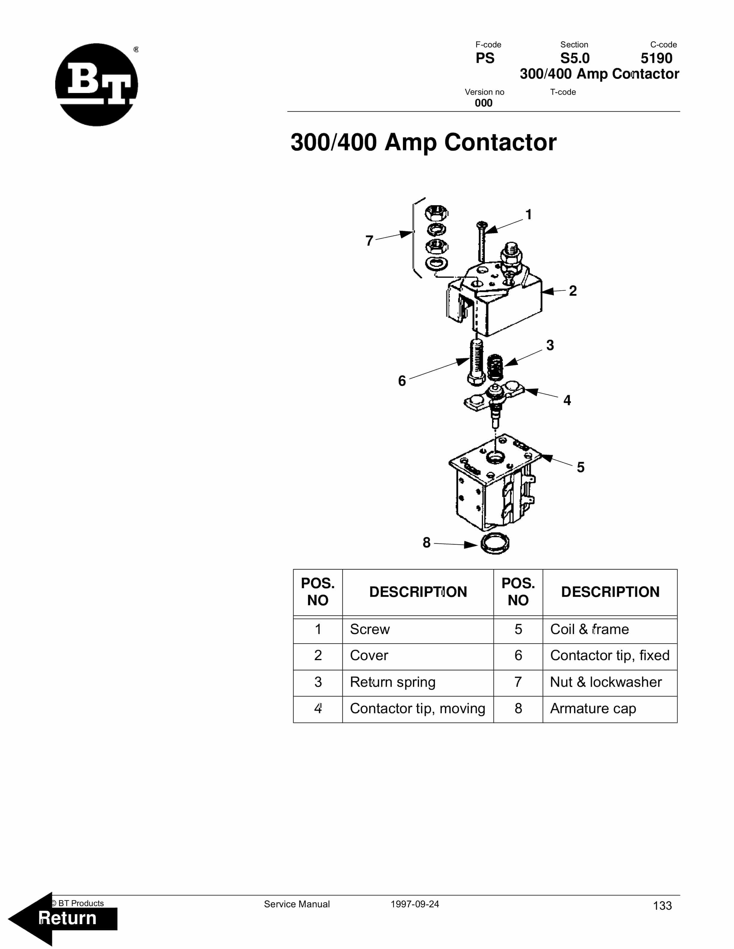
- 27. Charger BTCM – 8340
- 27.1. General
- 27.2. Installation
- 27.3. Function and use
- 27.3.1. Shut-off conditions
- 27.3.2. Delayed start and charging
- 27.3.3. Extra charging
- 27.3.4. Equalisation charge
- 27.3.5. Current and voltage characteristics
- 27.3.6. Safety shut-off
- 27.4. Display and keyboard
- 27.4.1. Reading analog measurement values
- 27.4.2. Error indication and error messages
- 27.4.3. Reading statistics from the previous charging process
- 27.4.4. Reading long-term statistics
- 27.4.5. Saving parameters in general.
- 27.4.6. Reading parameters
- 27.4.7. Battery specific parameters
- 27.4.8. Charger specific parameters
- 27.4.9. Mains voltage codes
- 27.4.10. Other functions
- 27.4.11. Changing of parameters
- 27.5. Service and maintenance
- 27.5.1. Resetting the statistics, code 31
- 27.5.2. Calibrating measurement values
- 27.5.3. Modifying the charging characteristics
- 27.5.4. Printing to a printer
- 27.6. Trouble shooting
- 27.6.1. Error messages, analysis and actions
- 27.7. Service actions
- 27.7.1. Switching to timer charging
- 27.7.2. Replacing the display card
- 27.7.3. Replacing the computer board
- 27.7.4. Replacing the motherboard
- 27.7.5. Replacing the diodes
- 27.8. Preventive maintenance
- 28. Control/computer equipment – 8700
- 28.1. General
- 28.2. Connection
- 28.3. Layout
- 28.3.1. Main program screen
- 28.3.2. Nodes
- 28.3.3. Icons
- 28.3.4. Tool buttons and menu bar
- 28.3.5. Information window
- 28.3.6. Status bar
- 28.4. Connection function
- 28.5. Disconnection function
- 28.6. Downloading program function
Rate this product
You may also like
BT Service Manual PDF
BT D-Series CBD40, CBD45, CBD50 Use And Maintenance Handbook 0337308R1CE
$30.00
BT Service Manual PDF
$30.00
BT Service Manual PDF
BT CMX60, CMX80 Electric Center Riding Pallet Truck Service Manual 302825-000
$30.00