


Caterpillar Operator Manual PDF
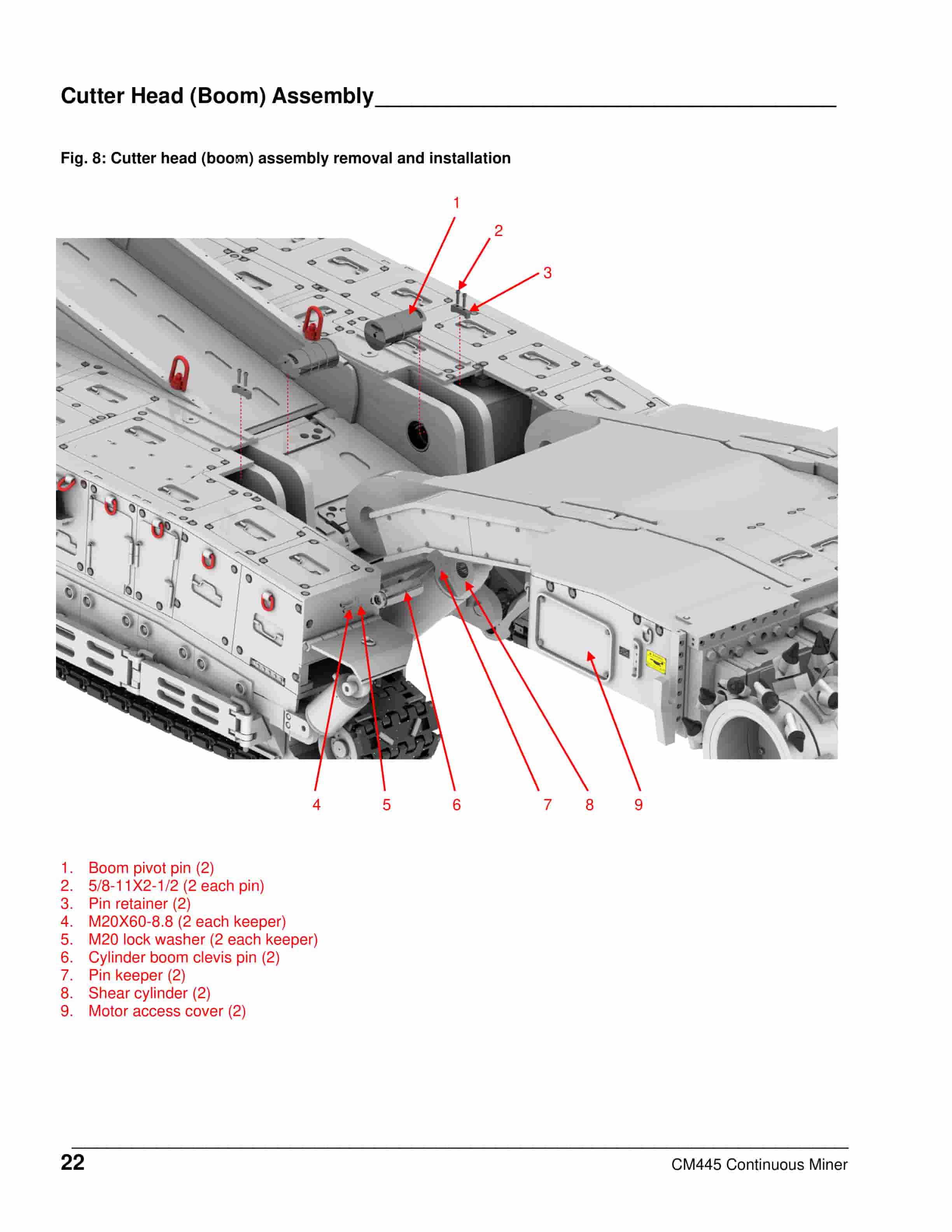
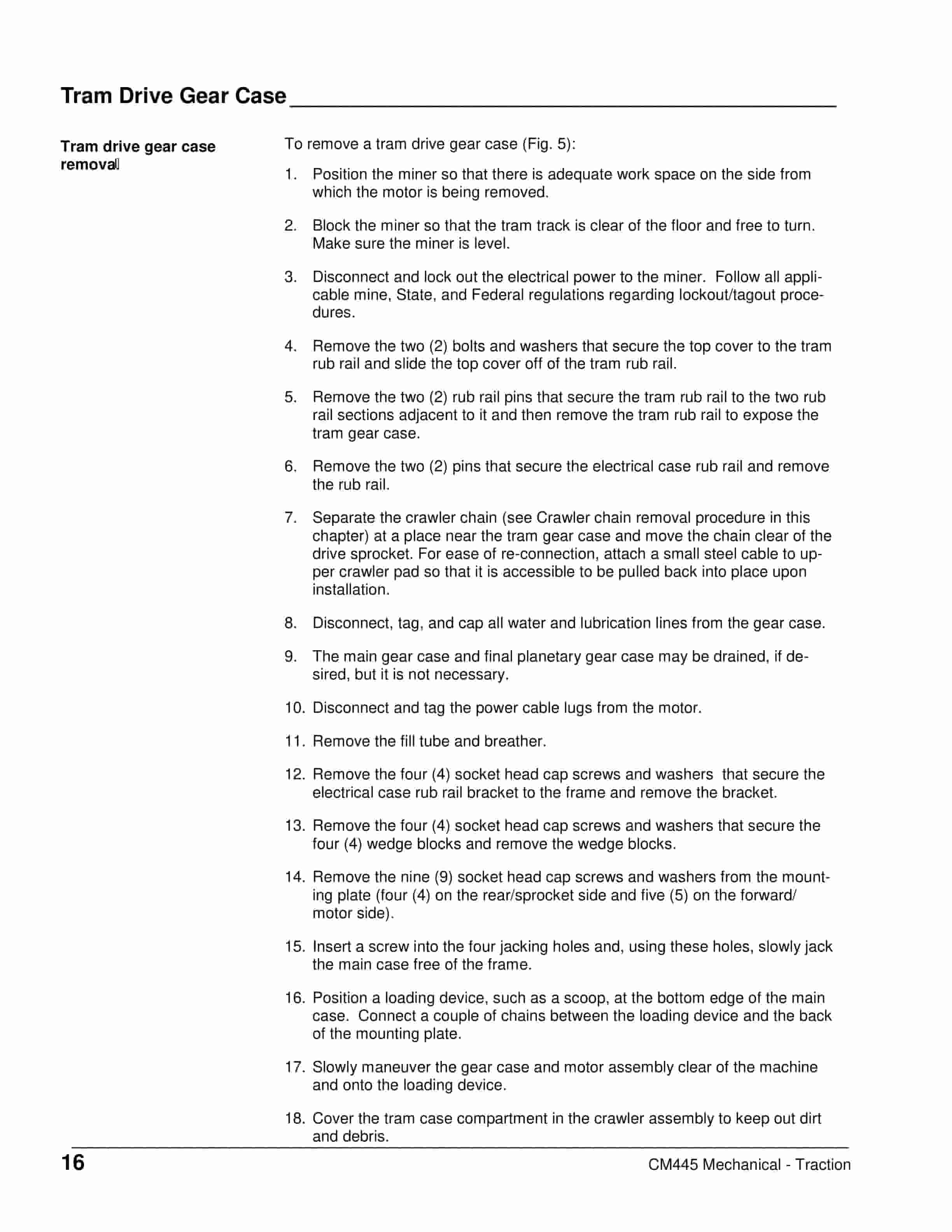
Caterpillar CM445 Continuous Miner Operation And Maintenance Manual A6474X367
Caterpillar Operator Manual PDF
Caterpillar BUC-SCR 120 Series Battery Charger Operation And Maintenance Manual BI001952
Caterpillar Operator Manual PDF
Caterpillar CM445 Continuous Miner Operation And Maintenance Manual A6474X363
Caterpillar Operator Manual PDF
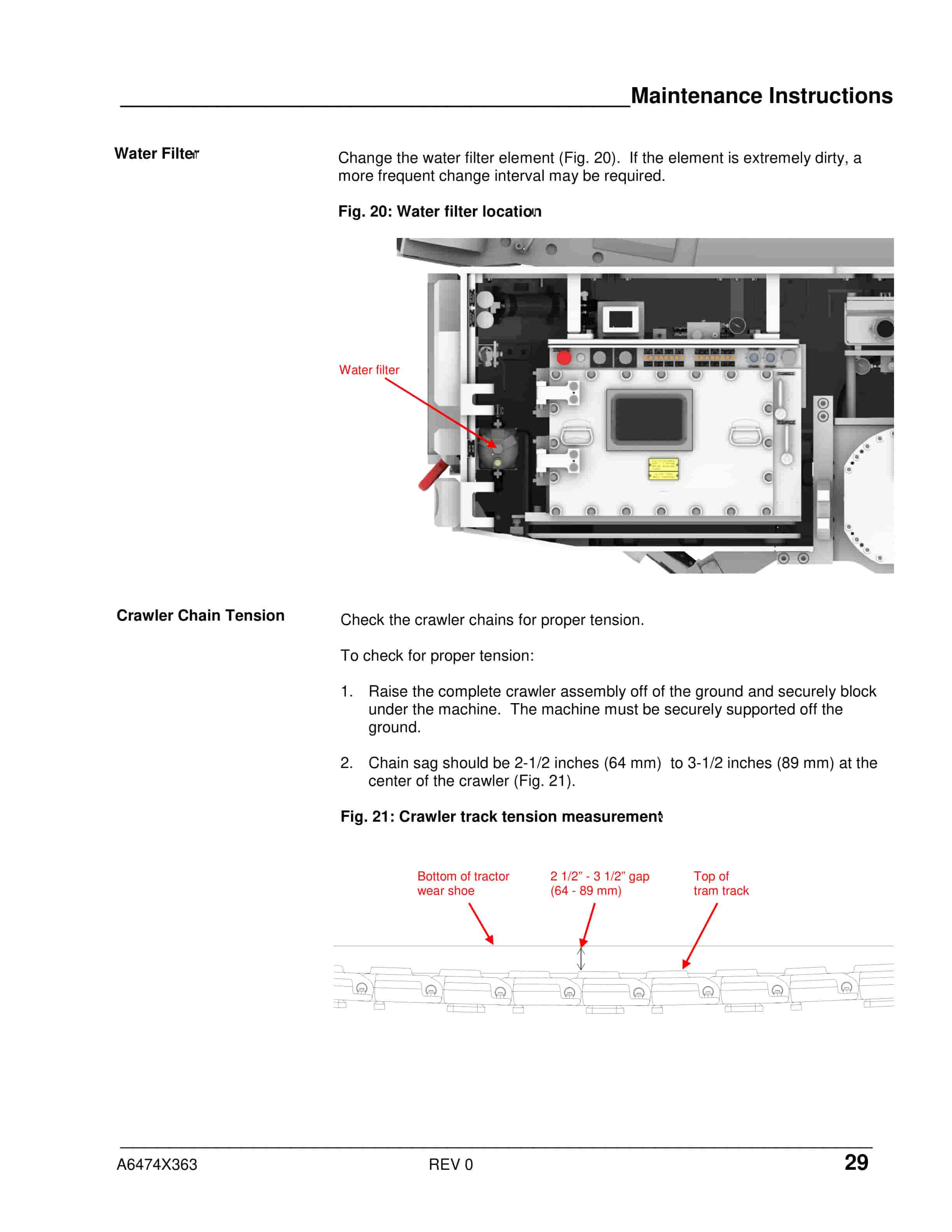
Caterpillar CM345 Continuous Miner Operation And Maintenance Manual BI001592-02
Caterpillar Operator Manual PDF
Caterpillar BSL PF 6-1542 Operating Manual 0010 452 600 BA 00

Caterpillar Operator Manual PDF
Caterpillar CM445 Continuous Miner Operation And Maintenance Manual A6474X365

Caterpillar Operator Manual PDF
Caterpillar CM345 Continuous Miner Operation And Maintenance Manual BI001589
Caterpillar Operator Manual PDF
Caterpillar CM210 Continuous Miner Operation And Maintenance Manual A6474X350

Caterpillar Operator Manual PDF
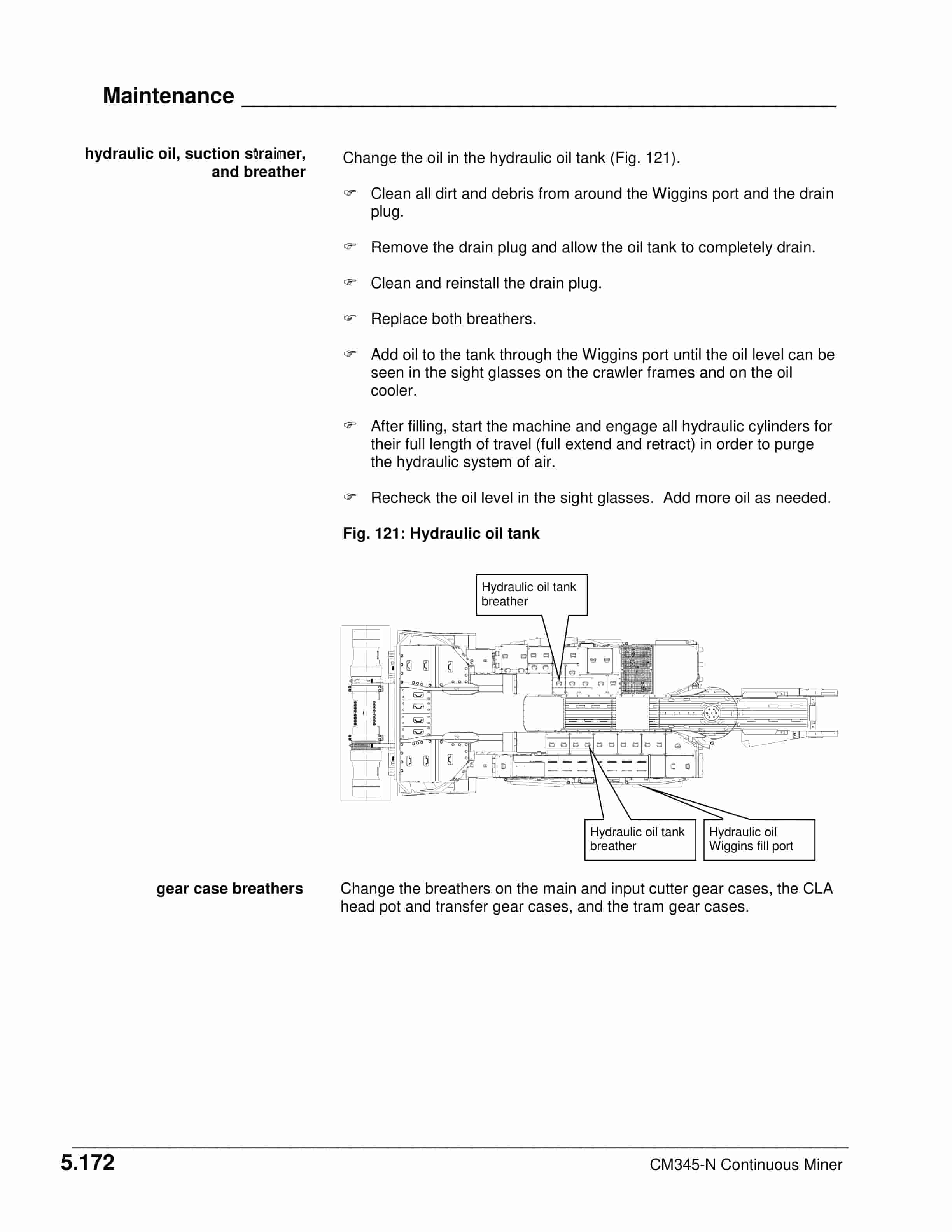
Caterpillar CM345-N Continuous Miner Operation And Maintenance Manual A6474X315